


Start-up, calibration and operation of the burner
27
20035606
GB
5.4
Air/fuel control and power modulation system
The air/fuel and power modulation system installed on burner se-
ries provides, a set of integrated functions ensuring top level ener-
gy and operational performance from the burner, both for single
and grouped burners (e.g. boiler with a double combustion cham-
ber or several generators in parallel).
The system includes the following basic functions:
air and fuels are supplied in correct quantities by positioning
the valves by direct servo-control, thus avoiding the possibility
of play typical of systems used for traditional modulating burn-
ers, in which settings are obtained by levers and a mechanical
cam;
burner power is modulated according to the load required by
the system, while boiler pressure or temperature is maintained
at set operating values;
Further interfaces and computer communication functions for re-
mote control or integration in centrally supervised systems are
available according to the system’s configuration.
NOTE
The first start-up and all further operations concerning internal set-
tings of the control system or expansion of basic functions, are ac-
cessed with a password and are reserved for technical service
personnel specifically trained for internal programming of the in-
strument and for the specific application obtained with this burner.
The first start-up and curve synchronization manual is supplied with
the burner.
The complete manual for checking and setting all parameters will
be provided on application.
5.4.1
Combustion air adjustment
Fuel/combustion air must be synchronized with the relevant ser-
vomotors (air and oil) by storing a setting curve by means of the
electronic cam.
To reduce pressure loss and to have a wider adjustment range,
it is best to set the servomotor to the maximum output used, as
near to maximum opening (90°) as possible.
On the butterfly valve, the fuel’s partial setting adjustment based
on required output, with the servomotor fully open, is made by
turning the pressure adjustment screw 5)(Fig. 22, page 23).
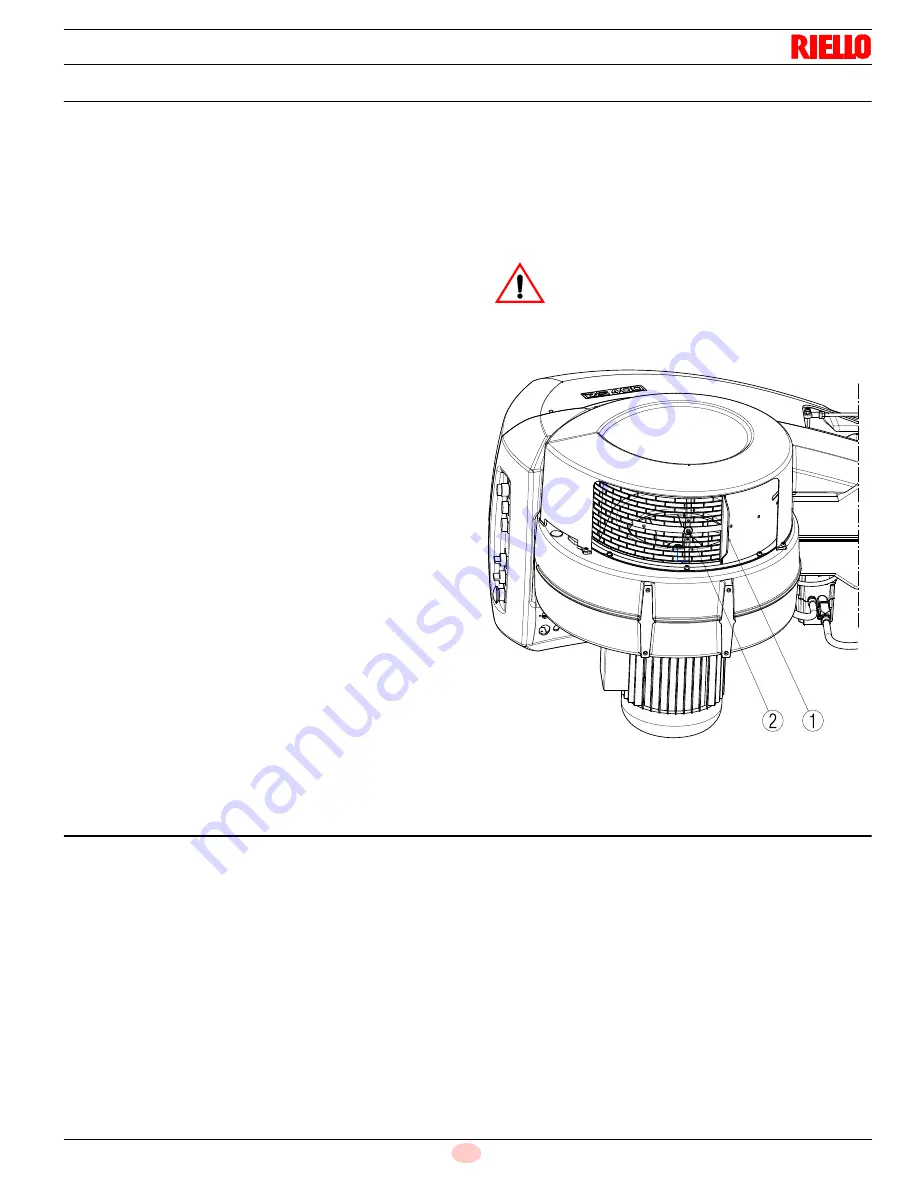
5.4.2
Air gate adjustment for maximum output
Set the servomotor to maximum opening (near 90°) so that the air
butterfly valves are fully open.
Loosen screw 2)(Fig. 30) under the burner’s intake and close grille
1) progressively until you achieve the required output.
The only time reducing intake to a partial setting is not necessary
is when the burner is working at the top of the operating range.
5.5
Rotation of fan motor
After turning the power on to the burner, check the motor rotation.
If the phase sequence is not correct, the burner does not fire.
WARNING
We recommend you achieve the maximum output
required manually, and adjust intake to the partial
setting, define gas pressure and adjust the combus-
tion head before completing the setting and storing
the fuel/combustion air synchronization curves.
D3094
Fig. 30
Summary of Contents for RL 300
Page 2: ......
Page 33: ...Appendix Spare parts 31 20035606 GB A Appendix Spare parts ...
Page 38: ...20035606 36 GB Appendix Electrical panel layout ...
Page 39: ...Appendix Electrical panel layout 37 20035606 GB ...
Page 41: ...Appendix Electrical panel layout 39 20035606 GB ...
Page 42: ...20035606 40 GB Appendix Electrical panel layout ...
Page 43: ...Appendix Electrical panel layout 41 20035606 GB 0 1 0 ...
Page 44: ...20035606 42 GB Appendix Electrical panel layout 0 0 0 1 0 2 0 0 0 0 0 0 0 30 3 3 0 0 1 0 ...


