


2694
5
GB
3.4
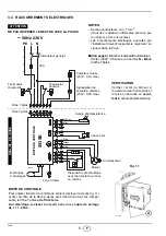
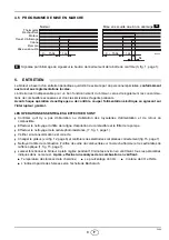
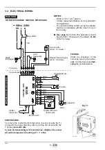
ELECTRICAL WIRING
ESEGUITO IN FABBRI
C
A
WARNING
DO NOT EXCHANGE NEUTRAL WITH PHASE
7 pin plug
7 pole socket
Black
White
Capacitor
Main switch
T6A
Motor
Safety
Blue
Oil valve
Hour counter
(230V - 0.1A max.)
Limit
Remote lock-out signal
(230V - 0.5A max.)
Ignition
electrodes
Brown
Burner-earth
CAR
RIED
-OUT IN
THE FAC
T
ORY
Heater with start
thermostat
553
S
E
CONTROL BOX
D1912
Photoresistance
PE L
N
~
50Hz 230V
Blue
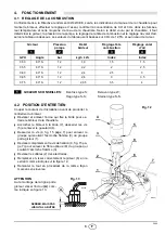
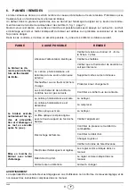
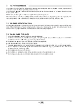
CONTROL BOX
To remove the control-box from the burner, loosen screw (
A,
fig. 11)
and pull to the arrow direction, after removing all components, the
7 pin plug
and earth wire
.
In case of disassembly of the control box, retighten the screw
(A) with a torque wrench setting of 1 – 1.2 Nm.
TESTING
Check the shut-down of the
burner by opening the thermo-
stats and the lock-out by
dark-
ening
the photoresistance.
S7186
Fig. 11
A
thermostat
NOTES:
– Wires of min. 1 mm
2
section.
(Unless requested otherwise by local standards
and legislation).
– The electrical wiring carried out by the installer
must be in compliance with the rules in force in
the Country.
(See page 4).
Connect the automatic shut-off
device (230V - 0.5A max.) to the clamps
N - B4
of the 7 pin plug.
thermostat