21
20162463
GB
Installation
5.12
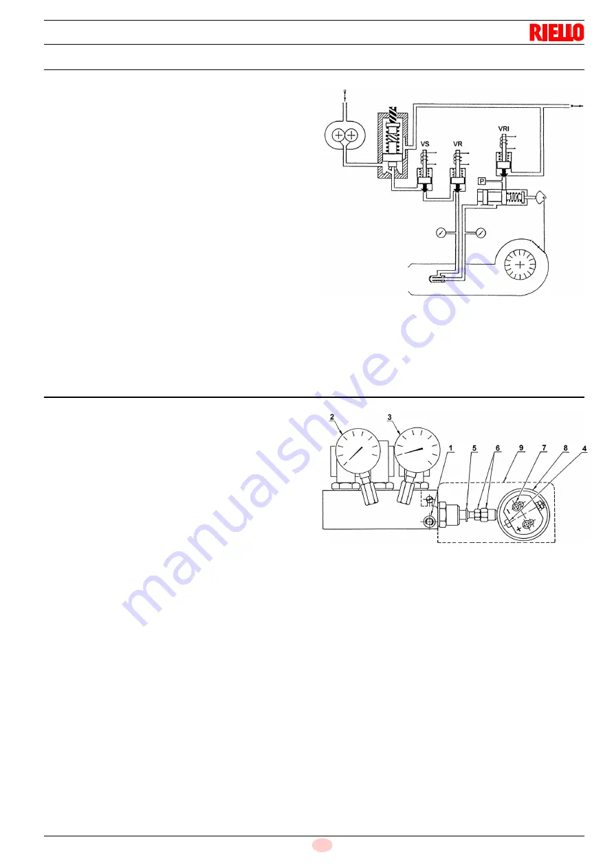
Hydraulic operation diagram
Oil pressure switch
In the event of excessive counter-pressure on the fuel return line,
the burner is brought to a halt (Fig. 18)
It is factory set at 1.5 bar. If the burner is fed by a pressure Pa ring
circuit, it must be adjusted to Pa+1.5 bar.
If the lock halt takes place (P position), press the red reset button
on the oil pressure switch.
Maximum oil pressure switch
The maximum oil pressure switch measures the pressure imme-
diately downstream of the regulator. It has been factory set to 3
bar. If the pressure exceeds the set value while operating, the
opening of the contact prevents the burner form operating, in
some cases putting it in a lockout condition.
It should be regulated to a pressure about 2-3 bar above the ac-
tual pressure of the return line pump.
Minimum oil pressure switch
This has the function of preventing the burner from operating if
there is insufficient spray pressure.
It should be adjusted to about 4 bar lower than the spray pres-
sure.
It has been factory set to 5 bar.
5.13
Pressure variator
To calibrate the eccentric 8):
remove the cover 9), loosen the screws 7), turn the screw 4)
until the desired eccentricity is obtained;
by turning screw 4) to the right (+) the eccentricity increases,
thereby increasing the difference between the maximum and
minimum capacity of the nozzle;
by turning screw 4) to the left (-) the eccentricity decreases,
thereby decreasing the difference between the maximum
and minimum capacity of the nozzle.
At every eccentricity variation it may be necessary to offset the
stroke by means of the nut and locknut 6).
Note
•
For a correct calibration, the eccentric 8) must operate on the
entire range of travel of the servomotor (20° ÷ 130°): a
pressure variation must correspond to each servomotor
variation.
•
Never drive the variator piston fully home: the stop ring 5)
determines the maximum stroke.
•
At the end of the adjustment, manually check that between
20° and 130° there is no sticking and that the maximum and
minimum pressures correspond to the one selected
according the diagram (A).
•
If at the maximum delivery of the nozzle (maximum pressure
on the return line) pressure oscillations can be seen on the
pressure gauge 3), slightly reduce the pressure until they
disappear.
Key
1
Pressure switch connection
2
Delivery pressure gauge
3
Return pressure gauge
4
Eccentric adjustment screw
5
Piston stop ring
6
Piston calibration nut and lock nut
7
Eccentric locking screws
8
Variable eccentric
9
Cover
Fig. 18
S8808
BURNER HALT
CONDITION
Fig. 19
D3437
Summary of Contents for GI/EMME 1400
Page 2: ...Translation of the original instructions ...
Page 55: ...53 20162463 GB Appendix Electrical panel layout 0 0 0 1 0 2 0 0 0 0 0 0 0 30 3 3 0 0 1 0 ...
Page 56: ...20162463 54 GB Appendix Electrical panel layout 0 1 2 2 2 0 ...
Page 57: ...55 20162463 GB Appendix Electrical panel layout 0 1 2 2 2 0 ...
Page 60: ...20162463 58 GB Appendix Electrical panel layout 0 1 2 2 2 3 2 2 2 2 2 2 2 2 2 2 2 3 2 4 56 ...
Page 65: ...63 20162463 GB Appendix Electrical panel layout 011 234 1 5 6 732 0 1 31 8 2 0 9 9 ...
Page 66: ...20162463 64 GB Appendix Electrical panel layout 0 ...
Page 71: ...69 20162463 GB Appendix Electrical panel layout 0 0 0 1 0 2 0 0 0 0 0 0 0 30 3 3 0 0 1 0 ...
Page 72: ...20162463 70 GB Appendix Electrical panel layout 0 1 2 2 2 0 ...
Page 73: ...71 20162463 GB Appendix Electrical panel layout 0 0 0 1 0 2 0 0 0 0 0 0 0 0 0 0 1 0 ...
Page 75: ...73 20162463 GB Appendix Electrical panel layout 0 1 2 2 2 3 2 2 2 2 2 2 2 2 2 2 2 3 2 4 56 ...
Page 78: ......
Page 79: ......


