background image

20176605

12 

GB

Technical description of the burner

4.10

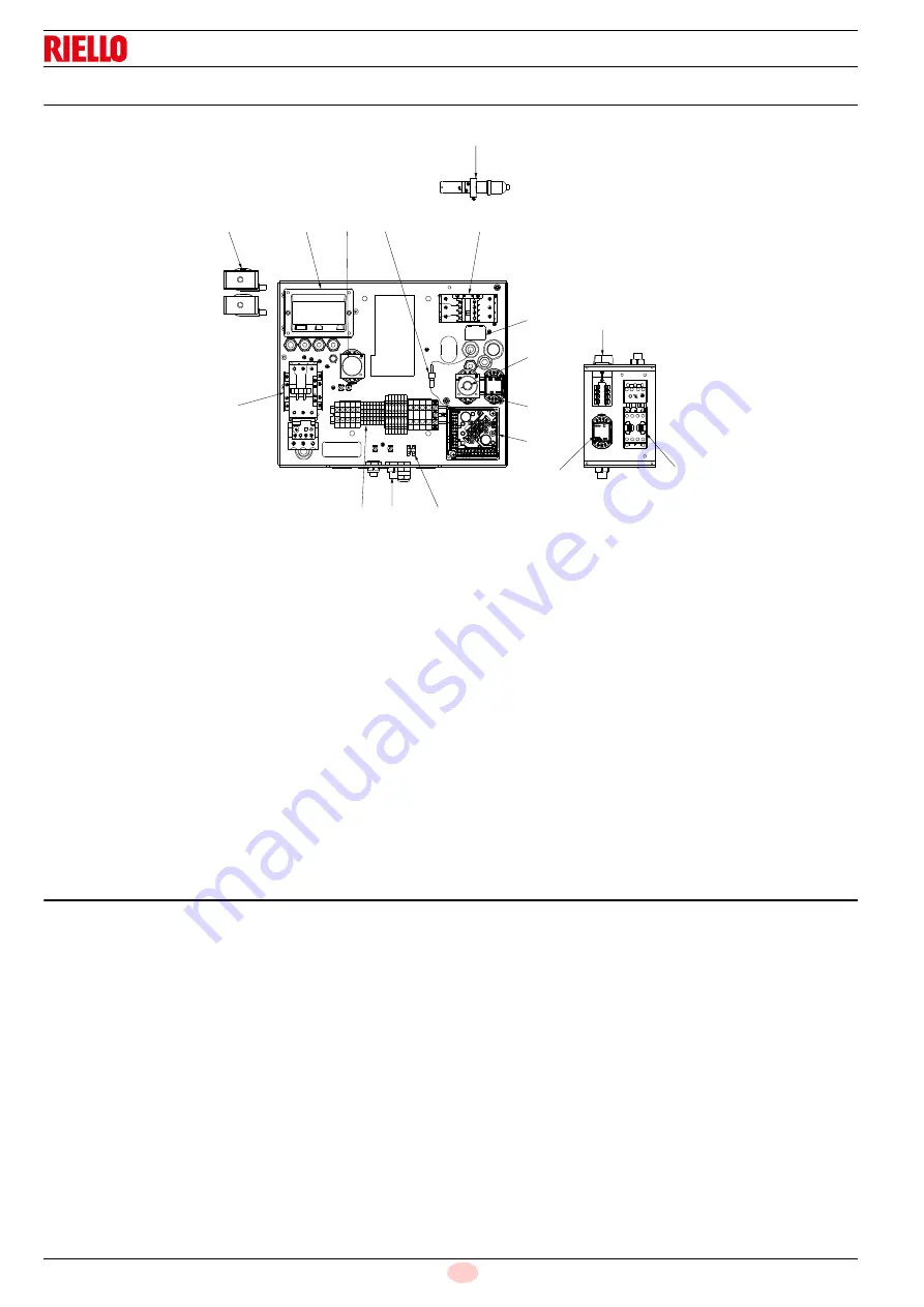
Electrical panel description 

1

Contactor and thermal relay for fan motor (only for direct
start-up)

2

Contactor and thermal relay for pump motor

3

Plug-socket on servomotor cable

4

Resistors contactor

5

Terminal board

6

Relay

7

Time relay

8

Relay

9

Electronic thermostat

10 Control box base
11 Flame sensor
12 Coils for oil valves
13 Suppressor (only for ENNE/EMME 3000-4500 models)
14 Cable grommets for external wirings (to be carried out by

the installer)

15 Ignition transformer
16 Selector switch 

OIL-0-GAS

17 Terminal board

4.11

Burner equipment 

Seal for gas train  . . . . . . . . . . . . . . . . . . . . . . . . . . . . . . . .  No. 1
Extensions . . . . . . . . . . . . . . . . . . . . . . . . . . . . . . . . . . . . .  No. 2
Screws . . . . . . . . . . . . . . . . . . . . . . . . . . . . . . . . . . . . . . .  No. 12
Insulating flange gasket . . . . . . . . . . . . . . . . . . . . . . . . . . .  No. 1
Flexible hoses  . . . . . . . . . . . . . . . . . . . . . . . . . . . . . . . . . .  No. 2
Nipples . . . . . . . . . . . . . . . . . . . . . . . . . . . . . . . . . . . . . . . .  No. 2
Cable grommets. . . . . . . . . . . . . . . . . . . . . . . . . . . . . . . . .  No. 4
Washers . . . . . . . . . . . . . . . . . . . . . . . . . . . . . . . . . . . . . . .  No. 8
Instruction. . . . . . . . . . . . . . . . . . . . . . . . . . . . . . . . . . . . . .  No. 1
Spare parts list . . . . . . . . . . . . . . . . . . . . . . . . . . . . . . . . . .  No. 1

12

15

1

14

5

10

6

7

13

3

9

4

16

8

2

11

17

Fig. 5

20181970

Summary of Contents for ENNE/EMME 1400

Page 1: ...12 2021 Dual fuel heavy oil gas burners Two stage progressive or modulating operation CODE MODEL TYPE 20169213 ENNE EMME 1400 618 M 20169214 ENNE EMME 2000 619 M 20169215 ENNE EMME 2000 619 M 2016921...

Page 2: ...Translation of the original instructions...

Page 3: ...ntrol box RFGO A22 13 4 13 Servomotor SQM40 14 5 Installation 15 5 1 Notes on safety for the installation 15 5 2 Handling 15 5 3 Preliminary checks 15 5 4 Operating position 16 5 5 Preparing the boile...

Page 4: ...8 3 Minimum gas pressure switch 32 6 8 4 Maximum oil pressure switch 33 6 8 5 Air bleeding 33 6 8 6 Gas butterfly valve 33 6 9 Spray temperature adjustment 34 6 9 1 Electronic adjustment thermostat 3...

Page 5: ...MME 4500 618 M 619 M 620 M 621 M These products are in compliance with the following Technical Standards EN 676 EN 267 EN 12100 and according to the European Directives MD 2006 42 EC Machine Directive...

Page 6: ...ried out correctly may cause damage to the machine and or injury to people DANGER DANGER LIVE COMPONENTS This symbol indicates operations which if not carried out correctly lead to electric shocks wit...

Page 7: ...vent of damage to things or injury to people if such damage injury was due to any of the following causes incorrect installation start up use and maintenance of the burner improper incorrect or unreas...

Page 8: ...tenance Only those parts envisaged by the manufacturer can be replaced 3 2 Personnel training The user is the person body or company that has acquired the machine and intends to use it for the specifi...

Page 9: ...nisation Class 2 EN267 Class 3 EN676 Series ENNE EMME Size Fuel Natural gas Light oil Adjustment Electrical supply of the system 3 400 50 3 230 50 Voltage of auxiliaries 230 50 110 50 60 4500 TC Emiss...

Page 10: ...E 3000 ENNE EMME 4500 Type 618 M 619 M 620 M 621 M Minimum Modulation Output Kcal h 350 000 500 000 750 000 1 000 000 kW 407 581 872 1 163 Minimum operating output Kcal h 700 000 1 000 000 1 500 000 2...

Page 11: ...230 400V 10 50 Hz 3N 400V 50 Hz Fan motor IE3 rpm kW V A 2900 3 230 400 9 7 5 6 2900 4 230 400 13 3 7 2930 9 2 230 400 28 6 16 5 2915 15 400 690 26 8 15 5 Pump motor IE3 rpm kW V A 1440 1 1 230 400 4...

Page 12: ...chamber dimensions are clearly smaller than those indicated in the diagram consult the manufacturer The firing rates were obtained in special test boilers according to EN 676 standard In Fig 3 you can...

Page 13: ...t 7 Control box release push button with lock signal 8 Head drive rod 9 Servomotor 10 Air adjustment cam 11 Max gas pressure switch 12 Gas pressure socket to sleeve 13 Gas regulator 14 Return pressure...

Page 14: ...t 10 Control box base 11 Flame sensor 12 Coils for oil valves 13 Suppressor only for ENNE EMME 3000 4500 models 14 Cable grommets for external wirings to be carried out by the installer 15 Ignition tr...

Page 15: ...ons Do not confuse the powered conductors with the neutral ones Ensure that spliced wires cannot get into contact with neighbouring terminals Use adequate ferrules Arrange the H V ignition cables sepa...

Page 16: ...ety reasons the servomotor must be checked after long periods of non use Technical data ATTENTION To avoid accidents material or environmental damage observe the following instructions Avoid opening m...

Page 17: ...n air inside the boiler must be free from hazardous mixes e g chloride fluoride halogen if present it is highly recommended to carry out cleaning and maintenance more frequently ATTENTION Burner handl...

Page 18: ...ions 1 2 3 and 4 Fig 9 Installation 1 is preferable as it is the only one that allows the maintenance operations as described in this manual Installations 2 3 and 4 allow operation but make maintenanc...

Page 19: ...wires into the terminal strip 18 refit fork 7 securing it with screws 10 completely close the burner securing it with screws 3 fit stops 4 pin with cotter 2 gas butterfly tie rod 11 and hoses 6 slide...

Page 20: ...mmended nozzle Select the nozzle with nominal output slightly higher than the one actually required among the following types Angles of 45 50 are normally recommended For narrow combustion chambers us...

Page 21: ...n pressure To set the delivery range within which the nozzle must operate adjust the maximum and minimum fuel pressure on the nozzle re turn according to the diagrams shown Return pressure bar Return...

Page 22: ...required proceed as follows With the servo motor at 0 slacken screws 5 and push ring 6 under the variable profile cam in the direction of the arrow This reduces eccentricity and thus decreases travel...

Page 23: ...regulator calibrated as table below 8 Filter with resistor for oil viscosity 7 E 50 C 9 Burner pump 10 Degassing unit Tab H Explosion danger due to fuel leaks in the presence of a flammable source Pre...

Page 24: ...8 must operate over the full travel range of the servomotor 20 130 every variation of the servomotor must be matched by a variation in pressure Never give the variator piston a snug fit stop ring 5 se...

Page 25: ...Return line 3 Vacuometer connection 4 Pressure gauge connection 5 Pressure adjustment Pump TA3C4010 5 TA4C4010 7 NVBHRPDC NVBHRMDC Burner ENNE EMME 1400 ENNE EMME 2000 ENNE EMME 3000 ENNE EMME 4500 Mi...

Page 26: ...over 1200 kW 9 Gasket for flanged versions only 10 Pressure adjuster 11 Train burner adaptor supplied separately P2 Pressure upstream of valves adjuster P3 Pressure upstream of the filter L Gas train...

Page 27: ...r must use the required equipment during installation Fig 25 20167882 kW 1 p mbar G 20 G 25 ENNE EMME 1400 800 10 14 9 889 11 1 16 5 978 12 2 18 2 1067 13 3 19 8 1156 14 4 21 5 1244 15 6 23 2 1333 16...

Page 28: ...n the left Example N M 3000 with natural gas G20 Operation at maximum modulating output A pressure of 27 9 mbar column 1 corresponds in Tab J to an output of 2983 kW This value serves as a rough guide...

Page 29: ...When it is used as a UV control the system is considered as non permanent requiring one burner recycle every 24 hours Normally burner stopping is guaranteed by the boiler s thermostat pressure switch...

Page 30: ...t in the arrow direction to the right to carry out the thermal relay test 5 18 Motor rotation As soon as the burner starts place yourself in front of the cooling fan of the fan motor and check that it...

Page 31: ...the limit thermostat TL is closed the request is sent and the burner begins the starting cycle At first ignition there is a momentary drop in fuel pressure due to the filling of the nozzle piping This...

Page 32: ...indicate the presence of voltage stop the burner immediately and check the electric connections When the limit thermostat TL closes the heat request is sent and the burner begins the starting cycle 6...

Page 33: ...n follow what is described below for each cam Cam I RED 130 The same for all models Limits rotation toward maximum position ATTENTION Do not make any adjustments Cam II BLUE 0 The same for all models...

Page 34: ...he minimum gas pressure switch is to prevent the burner from operating in an unsuitable way due to too low gas pressure Adjust the minimum gas pressure switch Fig 33 after having adjusted the burner t...

Page 35: ...8 6 Gas butterfly valve The gas butterfly valve is equipped with an external adjustment see Fig 36 that can facilitate the following calibration of the cam in case of low pressure values available in...

Page 36: ...g the resistance and the plate pack as shown in the adjacent figure The same precautions should be taken when renewing the resist ances in contact with the thermostat probes If the pre heater should m...

Page 37: ...for oil 6s for gas operations MOTOR LOCK this is brought about by the overload cut out thermal relay when a phase is missing s 6 s 45 s 6 s 45 s 3 s 31 s 38 s 3 s 31 s 38 Fig 40 Normal Lock for start...

Page 38: ...switch to the minimum end of scale position Turn the air pressure switch knob to the maximum end of scale position The burner must stop in lockout Turn off the burner and cut off the power Disconnect...

Page 39: ...ndicators that activate as soon as they are powered 7 2 3 Checking and cleaning Combustion Carry out an analysis of the combustion flue gases Significant differences with respect to the previous measu...

Page 40: ...ompared to 20 of the maximum brightness press the reset button again 0 5sec to reset the standard operation of the signalling LEDs 7 2 4 Safety components The safety components should be replaced at t...

Page 41: ...e hoses are still in good condition Fuel tank Approximately every 5 years suck any water on the bottom of the tank using a separate pump Combustion If the combustion values measured before starting ma...

Page 42: ...ply from the burner by means of the system main switch DANGER Close the fuel shut off valve Wait for the components in contact with heat sources to cool down completely After carrying out maintenance...

Page 43: ...ED starting from the flame LED represents 20 of the signal power To exit the check mode function press the reset button the flame control will go back to the normal operating mode 8 3 Flame control lo...

Page 44: ...er open Damper closed Modulation Ignition Flame Status Icon Power OFF ON OFF Not ready Diagnostics Green Standby Green Servomotor movement Note 3 OFF Flashing Flashing OFF Green Waiting for closing Gr...

Page 45: ...cause material problems severe injuries or death It is the owner or user s responsibility to make sure that the equipment described is installed used and commissioned in compliance with the requiremen...

Page 46: ...lay fault Red 19 Combustion airflow switch fault in the rest position Red 20 UV no flame at the end of the 2nd safety time MTFI Red 21 Safety relay fault Red 22 Supervisor processor fault Red 23 Super...

Page 47: ...Red 52 Piloted valve feedback fault Red 53 Actuator feedback waiting time expired Red 54 Direct ignition valve feedback fault Red 55 Internal processor fault Red 56 UV false flame during operation Red...

Page 48: ...or fault Internal fault Replace the control device 16 No flame 1st safety time PTFI No flame at the end of the first safety time Inspect the system check the gas pressure check the UV scanner check th...

Page 49: ...system detected the presence of voltage on T17 at the wrong moment or there is no voltage when necessary Check the wiring and make sure that the earthing is appropriate If the problem persists contact...

Page 50: ...ories Parameter to be controlled Probe Output regulator Adjustment field Type Code Type Code Temperature 100 500 C PT 100 3010110 RWF50 2 RWF55 5 20100018 20101965 Pressure 0 2 5 bar 0 16 bar 0 25 bar...

Page 51: ...sories Thermal relay kit Gas trains in compliance with EN 676 Please refer to manual Bruciatore Code ENNE EMME 3000 20163347 ATTENTION The installer is responsible for the addition of any safety devic...

Page 52: ...5 Functional layout RFGO A22 6 Functional layout RFGO A22 7 Functional layout RFGO A22 8 Electrical wiring that is the responsibility of the installer 9 Electrical wiring that is the responsibility o...

Page 53: ...51 20176605 GB Appendix Electrical panel layout 001 2 3455 670 8 9 5 2939 2 76 42 5 3 29375 92986 4 001 001 001 001 A B A ENNE EMME 1400...

Page 54: ...20176605 52 GB Appendix Electrical panel layout 001 2 3455 670 8 9 5 2939 2 76 42 5 3 29375 92986 4 001 001 001 001 A B A ENNE EMME 2000...

Page 55: ...53 20176605 GB Appendix Electrical panel layout 0 1 2 3455 67 8 9 5 2939 2 76 42 5 3 29375 92986 4 0 0 0 0 A B A ENNE EMME 3000...

Page 56: ...1 2 3 4 4 2 2 5 2 2 2 2 5 2 5 2 2 5 2 2 2 2 5 6 7 7 7 6 7 7 7 8 6 9 7 8 7 7 9 9 6 7 9 7 7 9 6 7 7 9 7 8 6 7 8 7 7 8 96 7 9 7 9 7 9 6 7 7 7 9 6 9 9 7 9 7 9 7 9 6 7 7 7 9 6 7 9 7 7 9 6 7 7 7 6 9 7 7 9 7...

Page 57: ...ndix Electrical panel layout 0 0 0 0 0 1 2 3455 6 7 5 2737 8 9 2 1 42 5 3 273 5 7276 4 1 0 0 0 0 0 0 0 0 0 0 0 0 0 0 0 0 0 0 0 0 0 0 0 0 0 0 0 0 0 0 0 0 0 0 0 0 0 0 0 0 0 0 0 0 0 0 0 0 0 0 0 0 1 1 1 E...

Page 58: ...Appendix Electrical panel layout 0 0 0 0 0 1 2 3455 6 7 5 2737 8 9 2 42 5 3 273 5 7276 4 0 0 0 0 0 0 0 0 0 0 0 0 0 0 0 0 0 0 0 0 0 0 0 0 0 0 0 0 0 0 0 0 0 0 0 0 0 0 0 0 0 0 0 0 0 0 0 0 0 0 0 0 1 1 1...

Page 59: ...20176605 GB Appendix Electrical panel layout 0 0 0 1 2 3 4 5 0 60 0 7 7 5 8 9 5 4 4 5 5 5 5 4 0 0 0 1 2 3 4 5 0 60 0 7 7 5 8 4 8 4 A B A A A A C A A A A A A A A A A A A A A A A A A A B A A ENNE EMME 4...

Page 60: ...20176605 58 GB Appendix Electrical panel layout 0 1 1 1 ENNE EMME 1400 2000...

Page 61: ...59 20176605 GB Appendix Electrical panel layout 0 1 1 1 ENNE EMME 3000...

Page 62: ...20176605 60 GB Appendix Electrical panel layout 0 1 2 2 2 3 4 50 2 0 62 21 7 7 8 9 9 9 9 8 8 9 9 9 8 9 8 8 8 8 9 9 9 9 9 8 9 8 8 9 ENNE EMME 4500...

Page 63: ...61 20176605 GB Appendix Electrical panel layout 0 1 2 2 2 0 ENNE EMME 1400 2000...

Page 64: ...20176605 62 GB Appendix Electrical panel layout 0 1 2 2 2 0 ENNE EMME 3000...

Page 65: ...63 20176605 GB Appendix Electrical panel layout 0 1 1 1 ENNE EMME 4500...

Page 66: ...20176605 64 GB Appendix Electrical panel layout 0 ENNE EMME 1400 2000...

Page 67: ...65 20176605 GB Appendix Electrical panel layout 0 ENNE EMME 3000...

Page 68: ...20176605 66 GB Appendix Electrical panel layout 0 1 2 2 2 0 ENNE EMME 4500...

Page 69: ...67 20176605 GB Appendix Electrical panel layout 01 2 3 2 3 4 01 2 3 2 3 4 5 6 0 7 5 6 4 4 3 5 6 0 7 2 3 2 3 4 5 6 0 7 8 0 5 6 0 7 9 5 6 0 5 6 0 2 2 2 ENNE EMME 1400...

Page 70: ...20176605 68 GB Appendix Electrical panel layout 01 2 3 2 3 4 01 2 3 2 3 4 5 6 0 7 5 6 4 4 3 5 6 0 7 2 3 2 3 4 5 6 0 7 8 0 5 6 0 7 9 5 6 0 5 6 0 2 2 2 ENNE EMME 2000...

Page 71: ...69 20176605 GB Appendix Electrical panel layout 0012 0012 3 4 3 4 5 5 6 7 6 7 5 5 5 5 4 4 5 4 8 6 7 6 7 001 001 8 9 8 9 3 3 3 3 3 ENNE EMME 3000...

Page 72: ...20176605 70 GB Appendix Electrical panel layout 0 ENNE EMME 4500...

Page 73: ...71 20176605 GB Appendix Electrical panel layout 0 1 0 2 2 2 2 3 1 1 1 4 5 3 4 5 2 6 6 6 7 6 6 6 6 6 6 6 6 16 1 1 6 6 7 6 8 9 ENNE EMME 1400 2000...

Page 74: ...20176605 72 GB Appendix Electrical panel layout 0012 3 4 3 4 5 6 7 001 8 6 7 001 8 3 4 3 4 5 9 001 6 7 001 6 7 001 3 ENNE EMME 3000...

Page 75: ...73 20176605 GB Appendix Electrical panel layout 01123 4 5 01123 4 5 01123 6 7 112 8 6 7 4 5 9 112 8 6 7 112 112 6 7 112 ENNE EMME 4500...

Page 76: ...20176605 74 GB Appendix Electrical panel layout 0 1 1 1 1 2 3 2 0 0 0 4 5 3 4 5 1 6 6 6 7 6 6 6 6 6 6 6 6 06 0 0 6 6 7 6 8 9 ENNE EMME 3000...

Page 77: ...75 20176605 GB Appendix Electrical panel layout 0 1 1 1 1 2 3 2 0 0 0 4 5 3 4 5 1 6 6 6 7 6 6 6 6 6 6 6 6 06 0 0 6 6 7 6 8 9 ENNE EMME 4500...

Page 78: ...05 5 8 7 8 8 8 8 7 7 7 7 7 7 7 7 7 7 7 7 7 7 7 7 7 7 7 7 7 7 7 7 7 7 7 7 7 7 7 7 7 7 7 7 7 7 7 7 7 7 7 7 7 7 7 7 7 A A A A A 7 A A 7 A 80605 1 5 3 4 8 5 3 3 6 808 B 6 65 3 3 6 808 B 6 65 3 3 6 0 08 0...

Page 79: ...Relay K2 Relay KM Fan motor contactor KMP Pump motor contactor KT Time relay KT1 Triangle contactor KS1 Star contactor KL1 Line contactor KST1 Timing relay for switching from star to triangle KR Conta...

Page 80: ...Subject to modifications RIELLO S p A I 37045 Legnago VR Tel 39 0442 630111 http www riello it http www riello com...

Reviews: