


Start-up, calibration and operation of the burner
25
20026767
5.7
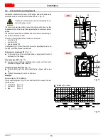
Minimum gas pressure switch
Adjust the minimum gas pressure switch (Fig. 31) after having per-
formed all the other burner adjustments with the pressure switch
set at the start of the scale.
With the burner operating at MAX output, increase adjustment
pressure by slowly turning the relative dial clockwise until the burn-
er locks out.
Then turn the dial anti-clockwise by 0.8” WC and repeat burner
starting to ensure it is uniform.
If the burner locks out again, turn the dial anti-clockwise again by
0.4” WC.
5.8
Flame signal measurement
Check the flame signal through the parameter 954, as indicated in
Fig. 32. The displayed value is expressed in percentage.
For further and specific information, please refer to the specific in-
struction manual.
The value during the operation must be higher than 24%. If at the
burner start-up the value is higher or equal of 18%, the burner locks
out due to the extraneous light.
The display (Fig. 32) shows parameter
954
: flashing on the left. On
the right, the flame’s intensity is displayed as a percentage.
Example:
954: 0.0
5.9
Final checks (with the burner working)
D9290
Fig. 31
S8171
P
V
h min s
%
Fig. 32
Open the control limit operation
Open the high limit operation
Æ
The burner must stop
Rotate the maximum gas pressure switch knob to the mini-
mum end-of-scale position (if installed)
Rotate the air pressure switch knob to the maximum end of
scale position
Æ
The burner must stop in lockout
Switch off the burner and disconnect the voltage
Disconnect the minimum gas pressure switch
Æ
The burner must not start
Cover the UV flame sensor
Æ
The burner must stop in lockout due to firing failure
WARNING
Make sure that the mechanical locking systems on
the different adjustment devices are fully tightened.
Summary of Contents for C9541400
Page 2: ......
Page 30: ...20026767 28 Appendix Spare parts A Appendix Spare parts...
Page 35: ......


