


20026767
20
Installation
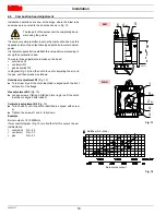
4.10 Gas train
It must be type-approved according to UL Standards and is sup-
plied separately from the burner.
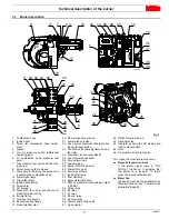
Key to layout
1
Gas input pipe
2
Manual valve
3
Pressure regulator
4
Low gas pressure switch
5
1
st
safety shut off valve
6
2
nd
safety shut off valve
7
Standard issue burner gasket with flange
8
Gas adjustment butterfly valve
9
Burner
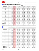
4.11
Gas pressure
The Tab. D is used to calculate manifold pressure taking into ac-
count combustion chamber pressure.
Tab. D
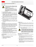
Gas manifold pressure measured at test point 1)(Fig. 19), with:
•
combustion chamber at 0” WC;
•
burner operating at maximum output;
•
column 1: gas ring R2-R3)(Fig. 13) adjusted as indicated in di-
agram (Fig. 14);
•
column 2: pressure loss at gas butterfly valve 8)(Fig. 18) with
maximum opening: 90°.
Calculate the approximate maximum output of the burner as fol-
lows:
subtract the combustion chamber pressure from the gas pres-
sure measured at test point 1)(Fig. 19);
find the nearest pressure value to your result in column 2 for
the burner in question;
read off the corresponding output on the left.
Example with natural gas G20
–
Maximum output operation
–
Gas ring 2-5)(Fig. 13) adjusted as indicated in diagram
(Fig. 14)
–
Gas pressure at test point 1)(Fig. 19)
= 3.69“ WC
–
Pressure in combustion chamber
= 0.79“ WC
3.69 - 0.79
= 2.90“ WC
A maximum output of 1136 MBtu/hr shown in Tab. D corresponds
to 2.90” WC pressure, column 1.
This value serves as a rough guide, the effective delivery must be
measured at the gas meter.
WARNING
See the accompanying instructions for the ad-
justment of the gas train.
Fig. 18
D2294
GAS PILOT LINE
MAIN GAS LINE
MBtu/hr
kW
p (“WC)
1
2
720
211
1.38
0.12
949
278
2.16
0.15
1136
333
2.90
0.19
1327
389
3.66
0.23
1515
444
4.21
0.27
1706
500
4.72
0.31
1894
555
5.12
0.35
2085
611
5.31
0.39
Fig. 19
D2786
Summary of Contents for C9541400
Page 2: ......
Page 30: ...20026767 28 Appendix Spare parts A Appendix Spare parts...
Page 35: ......


