


20040170
22
GB
Installation
5.11.3 Hydraulic connections
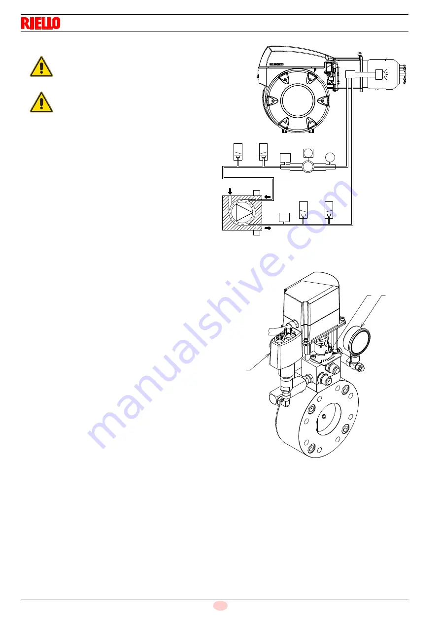
5.11.4 Hydraulic circuit diagram
Key (Fig. 18)
1
Pump suction
2
Pump return line and nozzle return line
3
Pump pressure regulator
4
Delivery safety valve
5
Delivery safety valve
6
Nozzle delivery line
7
Nozzle without interception rod
8
Nozzle return line
9
Pressure variator on nozzle return line
10 Pressure variator servomotor
11 Pressure switch on nozzle return line
12 Safety valve on nozzle return line
13 Safety valve on nozzle return line
14 Pressure switch on pump delivery line
M
Pressure gauges
V
Vacuometer connection
OPERATION
Pre-purging phase
:
valves 4), 5), 12) and 13) closed.
Ignition and operation phase
:
valves 4), 4), 12) and 13) open.
Stop:
All valves closed.
5.11.5 Pressure variator
The pressure variator (Fig. 19), incorporated in the oil circuit
valve group, makes it possible to vary the pressure on the nozzle
return line depending on the output required.
The pressure on the return line is adjusted by varying a section
by means of the rotation of the servomotor 23)(Fig. 5), which also
controls the gas butterfly valve at the same time.
Regulator to 0° (maximum opening) = minimum pressure on
nozzle return line.
Regulator to 90° (minimum opening) = maximum pressure
on nozzle return line.
The servomotor is controlled by the electronic cam 3) (Fig. 6);
thanks to this device, it is possible to set different curves for oil
and gas on the same servomotor (also for the air damper servo-
motor 4)(Fig. 5).
When
adjusting the gas
, it is recommended to adjust the
servomotor to about 90° to reduce leaks from the gas butter-
fly valve.
When
adjusting the oil
, the adjustment is done based on
the nozzle fitted and on the required degree of modulation;
in a situation of minimum firing rate, a rotation of 20° can be
enough.
Key (Fig. 19)
1
Nozzle return pressure gauge
2
Position indicator (0 ÷ 90) of the pressure variator
3
Maximum oil pressure switch on return circuit
CAUTION
Make sure that the flexible hoses to the pump
supply and return line are installed correctly.
WARNING
Follow the instructions below:
Tighten the flexible hoses with the supplied
gaskets.
Take care that the hoses are not stretched or
twisted during installation.
Place the pipes so that they are not crushed
or are in contact with hot parts of the boiler
and so it is possible to open the burner.
Finally, connect the other end of the flexible
hoses to the suction and return pipes.
M
P
M
V
1
4
5
P
9
10
11
12
13
14
8
7
6
V
2
Fig. 18
D11313
1
2
3
Fig. 19
D11322
Summary of Contents for 1311 T2
Page 2: ...Translation of the original instructions...
Page 46: ...20040170 44 GB Appendix Electrical panel layout 0 0 0 0 0 0 0 0...
Page 47: ...45 20040170 GB Appendix Electrical panel layout...
Page 49: ...47 20040170 GB Appendix Electrical panel layout...
Page 51: ...49 20040170 GB Appendix Electrical panel layout 0...
Page 52: ...20040170 50 GB Appendix Electrical panel layout 0 1 1 1 2 1 3 1 1 1 1 1 1 1 41 4 4 1 1 2 1...
Page 53: ...51 20040170 GB Appendix Electrical panel layout 0 0 1 2 0 0 3 3 3 0 1 4...
Page 57: ...55 20040170 GB Appendix Electrical panel layout 01 233 23 4 4 4 5 4 6 4 4 4 4 4 4 4 4 4 4 5 4...
Page 59: ......