background image

2306 

8

GB

4.5

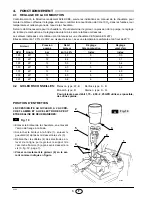
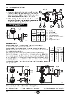
COMBUSTION HEAD SETTING 

(see fig. 11, page 7)

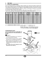
It depends on the output of the burner and is carried out by rotating clockwise or counterclockwise the setting
screw (5) until the set-point marked on the regulating rod (9) is level with the outside plane of the nozzle-holder
assembly (1).

In the sketch the combustion head is set for an output of 1.50 GPH at 12 bar.
The set-point 3 of the regulating rod (9) is at the same level with the outside plane of the nozzle-holder assem-
bly (1) as shown in the schedule.

4.6

AIR DAMPER ADJUSTMENT 

(see fig. 11, page 7))

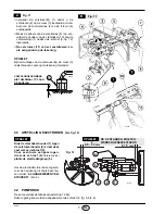
To vary the setting adjust the screw (7) after loosing the nut (8).

When burner shuts down the air damper automatically closes till a max. chimney depressure of 0.5 mbar.

4.7

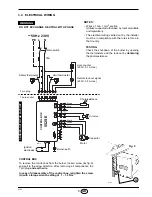
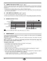
BURNER START-UP CYCLE

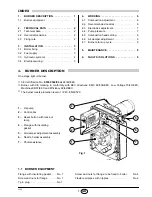
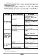
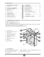
  Lock out is indicated by a lamp on the control box (3, fig. 1, page 1).

5.

MAINTENANCE

The burner requires periodic maintenance carried out by a qualified and authorised technician in conformity
with legislation and local standards.

Maintenance is essential for the reliability of the burner, avoiding the excessive consumption of fuel and
consequent pollution.

Before  carrying  out  any  cleaning  or control always first switch off the electrical supply to the
burner acting on the main switch of the system.

THE BASIC CHECKS ARE:

Check that there are not obstructions or dents in the supply or return oil pipes.

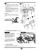
Clean the filter in the oil suction line and in the pump.

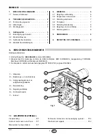
Clean the photoresistance, (7, fig. 1, page 1).

Check for correct fuel consumption.

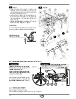
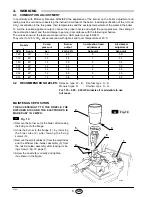
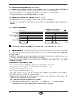
Replace the nozzle (see fig. 10, page 6) and check the correct position of electrodes (fig. 12, page 7). 

Clean the combustion head in the fuel exit area, on the diffuser disc.

Leave the burner working without interruptions for 10 min. and set rightly all the components stated in
this manual.  Then carry out a combustion check verifying:

Smoke temperature at the chimney;


Content of  CO

2

  ( % );

Content of CO (ppm);     

Smoke value according to opacity smokes index according to Bacharach scale.

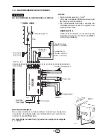
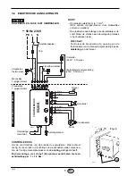
Lock-out due to failure to light    


C

Normal

D5029

~

12s

Thermostat

Motor

Ignition transformer

Valve

Flame

Lock-out lamp

~

12s

5 s

C

Summary of Contents for RG2 377T1

Page 1: ...en onderhoudsvoorschriften Montage und Bedienungsanleitung O l Gebl sebrenner Br leurs fioul Light oil burners Stookoliebranders CODE MODELL MODELE MODEL TYP TYPE 3737750 RG2 377 T1 3737753 RG2 377 T...

Page 2: ...riello be Wir best tigen hiermit dass die nachstehende Ger teserie dem in der CE Konformit ts erkl rung beschriebenen Baumuster entspricht und dass sie im Einklang mit den Anforde rungen des K E vom...

Page 3: ...nlage 4 3 4 Elektrisches Verdrahtungsschema 5 4 BETRIEB 6 4 1 Einstellung der Brennerleistung 6 4 2 Empfohlene D sen 6 4 3 Elektrodeneinstellung 7 4 4 Pumpendruck 7 4 5 Brennkopfeinstellung 8 4 6 Luft...

Page 4: ...mversorgung Einphasig 50Hz 230V 10 Motor Stromaufnahme 0 9A 2720 U min 285 rad s Kondensator 4 F Z ndtransformator Sekund rspannung 8 kV 16 mA Pumpe Druck 8 15 bar Leistungsaufnahme 0 18 kW 202 115 18...

Page 5: ...erdichtung 5 erweitern Mit den Schrauben 2 und falls erforderlich den Muttern 3 den Flansch 1 an der Kesselt r 4 mit Isolierdichtung 5 montieren siehe Abb 2 3 2 BRENNSTOFFVERSORGUNG Die lschl uche wer...

Page 6: ...Fu ventil in der Saugleitung verzichtet werden Endet die R cklauf Leitung ber dem lniveau wird auf der Saugseite zwingend ein Fu ventil ben tigt wobei dieses dann bei Verschmutzung Probleme verursache...

Page 7: ...len Bestim mungen entsprechen STEUERGER T Um das Steuerger t vom Brenner abnehmen zu k nnen m ssen die Steckverbindungen zu allen Komponenten der 7 polige Stecker sowie das Erdungskabel die Schraube A...

Page 8: ...p S B Monarch Typ R Steinen Typ S Q F r D sen mit 1 75 2 00 2 25 GPH vorzugsweise Vollkegel benutzen WARTUNGSPOSITION DIE ZUG NGLICHKEIT DER D SE DER STAUSCHEIBE UND DEN ELEKTRODEN WIRD DURCH FOLGENDE...

Page 9: ...Abbildung dargestellt 4 3 ELEKTRODENEINSTELLUNG Siehe Abb 12 4 4 PUMPENDRUCK Wird werksseitig auf 12 bar eingestellt Ver nderungen werden mit Hilfe der Schraube 4 Abb 5 Seite 4 vorgenommen S7640 B Abb...

Page 10: ...ereinstimmung mit den rtlichen Gesetzen und Vorschriften vom Kundendienst gewartet werden Die Wartung ist f r den umweltfreundlichen Betrieb des Brenners unbedingt notwendig Es wird dadurch sichergest...

Page 11: ...en Bedienungsanlei tung und durch das Eingreifen von unbefugtem Personal verursacht werden ist ausgeschlossen ST RUNGEN M GLICHE URSACHE ABHILFE Der Brenner f hrt bei der Ausl sung du Begrenzungstherm...

Page 12: ...rtifions par la pr sente que la s rie des appareils sp cifi e ci apr s est conforme au mod le type d crit dans la d claration de conformit CE qu il est fabriqu et mis en circula tion conform ment aux...

Page 13: ...s lectriques 5 4 FONCTIONNEMENT 6 4 1 R glage de la combustion 6 4 2 Gicleurs conseill s 6 4 3 R glage des lectrodes 7 4 4 Pression pompe 7 4 5 R glage t te de combustion 8 4 6 R glage volet d air 8 4...

Page 14: ...que Monophas e 50Hz 230V 10 Moteur 0 9A absorb s 2720 t min 285 rad s Condensateur 4 F Transformateur d allumage Secondaire 8 kV 16 mA Pompe Pression 8 15 bar Puissance lectrique absorb e 0 18 kW 202...

Page 15: ...laque de la chaudi re 4 la bride 1 par l interm diaire des vis 2 et si n cessaire des crous 3 en interposant le joint isolant 5 voir fig 2 3 2 ALIMENTATION DU COMBUSTIBLE Le br leur est pr quip pour r...

Page 16: ...as il n y a pas besoin de clapet de pied Dans le cas contraire le clapet de pied est indispensable Cette deuxi me solution est moins s re que la pr c dente en raison du manque d tanch it ventuel de ce...

Page 17: ...he apr s avoir d branch tous les composants la fiche 7 p les et le fil de terre Au remontage revisser la vis A avec une couple de serrage de 1 1 2 Nm Fiche 7 p les Prise 7 p les Noir Blanc Condensateu...

Page 18: ...W B Danfoss type S B Monarch type R Steinen type S Q Pour gicleurs avec d bit 1 75 2 00 2 25 GPH utiliser si possible des c nes pleins POSITION D ENTRETIEN L ACCESSIBILITE AU GICLEUR A L ACCRO CHE FL...

Page 19: ...cleur visser l crou 3 comme indiqu en figure ci dessous 4 3 REGLAGE DES ELECTRODES Voir fig 12 4 4 PRESSION POMPE Elle est r gl e 12 bar en usine Pour modifier ce r glage jouer sur la vis 4 fig 5 page...

Page 20: ...onsommations de combustible excessives et donc les missions d agents polluants Avant chaque op ration de nettoyage ou de contr le couper l alimentation lectrique en agissant sur l interrupteur g n ral...

Page 21: ...leur ne d marre pas la ferme ture du thermostat de limite Absence d alimentation lectrique V rifier la tension au bornier L1 N de la fiche 7 p les V rifier les fusibles V rifier que le thermostat de s...

Page 22: ......

Page 23: ...al wiring 5 4 WORKING 6 4 1 Combustion adjustment 6 4 2 Recommended nozzles 6 4 3 Electrodes adjustment 7 4 4 Pump pressure 7 4 5 Combustion head setting 8 4 6 Air damper adjustment 8 4 7 Burner start...

Page 24: ...Single phase 50Hz 230V 10 Motor Run current 0 9A 2720 rpm 285 rad s Capacitor 4 F Ignition transformer Secondary 8 kV 16 mA Pump Pressure 8 15 bar Absorbed electrical power 0 18 kW 202 115 189 140 16...

Page 25: ...5 Fix the flange 1 to the boiler door 4 using screws 2 and if necessary the nuts 3 interposing the insulating gasket 5 see fig 2 3 2 FUEL SUPPLY The burner is designed to allow entry of the oil suppl...

Page 26: ...urn valve is not re quired Should however the return line arrive over the fuel level a non return valve is required This solution however is less safe than previous one due to the possibility of leaka...

Page 27: ...all components the 7 pin plug and earth wire In case of disassembly of the control box retighten the screw A with a torque wrench setting of 1 1 2 Nm DO NOT EXCHANGE NEUTRAL WITH PHASE 7 pin plug 7 p...

Page 28: ...lavan type W B Danfoss type S B Monarch type R Steinen type S Q For 1 75 2 00 2 25 GPH nozzles it is advisable to use full cones MAINTENANCE POSITION THE ACCESSIBILITY TO THE NOZZLE THE DIFFUSER DISC...

Page 29: ...ly screw the nut 3 as shown in the figure below 4 3 ELECTRODES ADJUSTMENTS see fig 12 4 4 PUMP PRESSURE The pump leaves the factory set at 12 bar To change it act on pump pressure adjust screw 4 fig 5...

Page 30: ...with legislation and local standards Maintenance is essential for the reliability of the burner avoiding the excessive consumption of fuel and consequent pollution Before carrying out any cleaning or...

Page 31: ...the intervention of unqualified personnel FAULTS POSSIBLE CAUSES SOLUTION The burner doesn t start when the limit thermostat closes Lack of electrical supply Check presence of voltage in the L1 N clam...

Page 32: ......

Page 33: ...o be URL www riello be Met deze verklaren we dat de reeks toestellen zoals hierna vermeld in overeenstemming zijn met het type model beschreven in de CE verklaring van overeenstemming geprodu ceerd en...

Page 34: ...sche aansluitingen 5 4 WERKING 6 4 1 Regeling verbranding 6 4 2 Aangewezen verstuivers 6 4 3 Afstelling electroden 7 4 4 Pompdruk 7 4 5 Afstelling branderkop 8 4 6 Regeling van de luchtklep 8 4 7 Star...

Page 35: ...rische voeding Monofasig 50Hz 230V 10 Motor Opgenomen stroom 0 9A 2720 t min 285 rad s Condensator 4 F Ontstekingstransformator Secundair 8 kV 16 mA Pomp Druk 8 15 bar Opgeslorpt vermogen 0 18 kW 202...

Page 36: ...1 op de ketelplaat 4 met behulp van de schroeven 2 en indien nodig de moeren 3 en voeg de flensdichting 5 ertussen zie fig 2 3 2 BRANDSTOFTOEVOER In de fabriek werd de brander voorzien om de brandsto...

Page 37: ...nden In dat geval is een voetklep overbodig Bij een niveauverschil tussen beide leidingen is een voetklep noodzakelijk Deze tweede oplossing biedt echter minder zekerheid omdat de dichtheid van de voe...

Page 38: ...adat u alle componen ten de 7 polige mannelijke stekker en de aarding ontkoppeld heeft Bij hermontage de schroef A opnieuw aandraaien met een aandraaikoppel 1 1 2 Nm Vrouwelijke Zwart Wit Condensator...

Page 39: ...type W B Danfoss type S B Monarch type R Steinen type S Q Gebruik bij voorkeur voor verstuivers met debiet 1 75 2 00 2 25 GPH een volle verstuivingskegel ONDERHOUDSPOSITIE KUNT DE VERSTUIVER DE VLAMH...

Page 40: ...tekening hieronder 4 3 AFSTELLING ELECTRODEN zie fig 12 4 4 POMPDRUK De pomp verlaat de fabriek afgesteld op 12 bar Deze regeling kan worden aangepast met de schroef 4 fig 5 blz 4 S7640 B Fig 11 B 3...

Page 41: ...keren om uitermate hoog brand stofverbruik en dus hoge milieubelastende emissies te vermijden Alvorens de brander te reinigen of te controleren sluit de elektrische voeding af door op de hoofd schakel...

Page 42: ...er ontsteekt niet bij de sluiting van de limietther mostaat Geen elektrische voeding Geen stroom Check de spanning aan het klemmenbord L1 N van de 7 polige mannelijke stekker Check de zekeringen Contr...

Page 43: ...1 1 1 2 2 2 1 2 2 2 2 2 3 2 3 3 3 1 3 3 2 3 3 3 4 3 4 5 4 6 4 1 6 4 2 6 4 3 7 4 4 7 4 5 8 4 6 8 4 7 8 5 8 6 9 1 2 3 4 5 6 7 CE Reg N 0036 0344 03 92 42 CE EMC 89 336 EOK 73 23 98 37 92 42 IP X0D IP 40...

Page 44: ...kW diesel 6 mm2 s 20 C 50Hz 230V 10 0 9A 2720 285 rad s 4 F 8 kV 16 mA 8 15 bar 0 18 kW 202 115 189 140 168 10 28 230 280 11 83 83 106 4 5 4 5 D5707 255 95 0 3 4 5 kg h 35 45 55 kW 1 0 0 8 0 6 0 4 0 2...

Page 45: ...2306 3 GR 3 3 1 1 3 5 4 1 2 3 5 2 3 2 1 2 4 2 3 S7209 1 D4075 1 2 4...

Page 46: ...8 L i 8 mm i 10 mm 0 5 1 1 5 2 10 20 40 60 20 40 80 100 L i 8 mm i 10 mm 0 0 5 1 1 5 2 3 3 5 35 30 25 20 15 8 6 100 100 100 90 70 30 20 2 by pass 3 2 5 1 2 3 by pass 4 5 6 7 6 H max 4 m D5713 H max 4...

Page 47: ...2306 5 GR 3 4 9 7 1 1 2 Nm D1913 T6A 230 V 0 1A max 552SE PE L N 50Hz 230V 7 7 S7217 9 A 1 mm2 230V 0 5A max...

Page 48: ...Danfoss S B Monarch R Steinen S Q 1 75 2 00 2 25 GPH GPH 10 1 2 3 4 5 3 12 7 6 GPH bar kg h 4 1 00 60 12 4 0 0 0 9 1 10 60 12 4 4 1 3 1 1 25 60 12 5 0 2 3 4 1 50 60 12 6 0 3 3 8 1 75 60 12 7 0 4 4 5...

Page 49: ...2306 7 GR 11 1 2 3 4 6 4 1 10 3 12 11 3 4 3 12 4 4 12 bar 4 5 4 S7640 B 11 B 3 D5684 1 2 3 4 5 4 2 6 12 4 5 mm 4 5 0 5 mm 0 1 2 3 5 4 D5537...

Page 50: ...2306 8 GR 4 5 11 7 5 9 1 1 50 GPH 12 bar 3 9 1 4 6 11 7 7 8 0 5 bar 4 7 3 1 1 5 7 1 1 10 6 12 7 CO2 CO ppm Bacharach D5029 12s 12s 5s C C...

Page 51: ...2306 9 GR 6 3 1 1 L1 N 7 5...

Page 52: ......

Reviews: