2611
7
GB
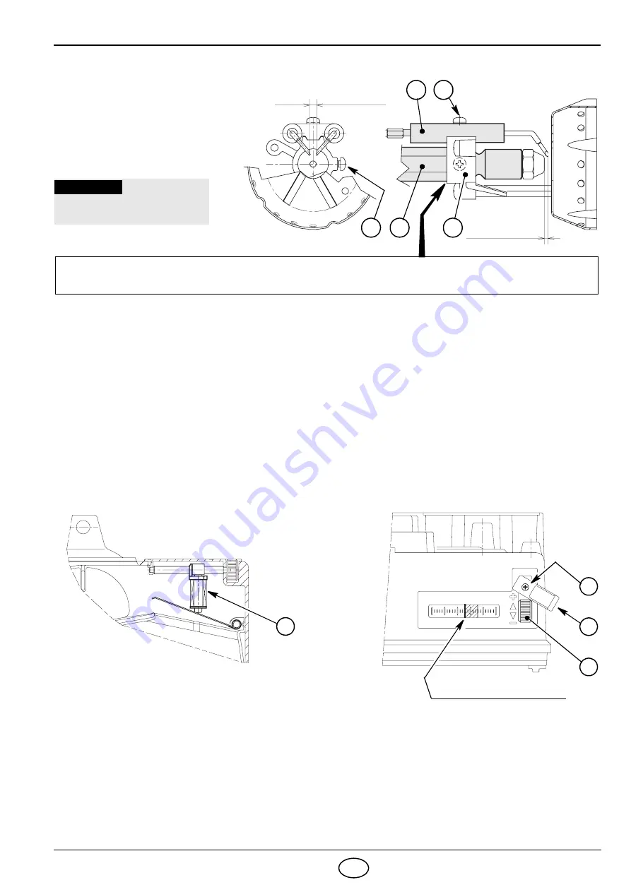
4.3 SETTING OF ELECTRODES,
(see fig. 11)
4.4 PUMP PRESSURE:
- The pump leaves the factory set at 12 bar.
- To change it act on pump pressure adjust screw (4, fig. 5, page 4).
4.5 AIR DAMPER ADJUSTMENT,
(see fig. 12)
➤
Use the knob (1) to make adjustments after slightly loosening the screw (2) and swinging out the protective
covering (3).
➤
Once adjustments have been made, place the protective covering (3) in its correct position and tighten the
screw (2).
➤
Fig. 12 shows adjustment of the air damper to a flow rate of 2.1 kg/h (notch 2.6).
➤
When burner shuts down the air damper automatically closes to a
max flue draw of 0.5 mbar.
➤
The burner is also fitted with an electromagnetic device (4) which prevents any slamming of the air damper on
burner starting, even in the presence of high boiler counter-pressure.
NOTE
In the event that the electromagnetic damper anti-slamming device (4, fig. 12) fails, the burner will not start as
the device is connected to the motor in series (see diagram page 5), and as such takes on a role of safety
device.
In the event of an anomaly, the burner may even be started without the device as it is connected to the circuit via
special connectors which allow it to be cut out. The male and female connectors on the device wire must be
disconnected and the motor connectors must be connected between them.
When resorting to this temporary solution, it is fundamental that an alternative adjustment of the air damper is
carried out.
2
– 0.2 mm
PLACE THE DIFFUSER DISC-HOLDER ASSEMBLY (1) ON THE NOZZLE-HOLDER (2) AND TIGHTEN
THE SCREW (3). For any adjustments, loosen the screw (4) and move the electrodes (5).
1
4.5
– 0.5 mm
0
D1676
3
2
5
4
To have access to the elec-
trodes carry out operation as
descr ibed in
chapter “4.2
RECOMMENDED NOZZLES”
(page 6).
Fig. 11
+
0.2
WARNING
MEASURES MUST BE
RESPECTED
Fig. 12
Adjustment reference side
D1693
2
3
1
4
D1691
0 1 2
4 5
3


