


2867
7
GB
Fig. 11
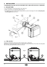
➤
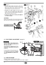
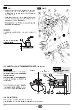
Remove nozzle-holder assembly (1) after loos-
ing screws (2) and nut (3), remove the small ca-
b l e s ( 4 ) f r o m t h e c o n t r o l b o x , t h e
photoresistance (6) and the socket (10).
➤
Withdraw the small cables (4) from the elec-
trodes, remove the diffuser disc-holder assem-
bly (11) from the nozzle-holder assembly (1)
after loosing screw (3, fig. 12).
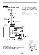
➤
Screw the nozzle (12) correctly and tighten it
as shown in figure.
ATTENTION
During the reassembly of the nozzle-holder assem-
bly screw the nut (3) as shown in the figure below.
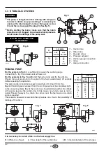
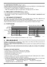
4.3
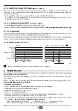
ELECTRODES ADJUSTMENT
(see fig. 12)
4.4
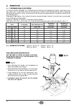
PUMP PRESSURE
The pump leaves the factory set at 12 bar.
To change it act on pump pressure adjust screw (4, fig. 5, page 4).
S7638
B
Fig. 11
B
3
TIGHTEN WITHOUT MOVING
BACKWARDS TO THE END
D5684
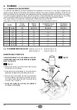
Lean the diffuser disc-holder assem-
bly (1) on the nozzle-holder (2) and
lock it by screw (3).
For prospective adjustments of the
electrodes assembly (4), loosen
screw (5).
WARNING
To have access to the electrodes carry
out operation as described in chapter
“4.2 RECOMMENDED NOZZLES”
(page 6).
D5022
4.5
– 0.5 mm
0
2.5
±
0.2 mm
3
+ 0.5 mm
0
WARNING
MEASURES
MUST BE RESPECTED
Fig. 12
1
2
3
5
4
Summary of Contents for 3736420
Page 2: ...4...