background image

17

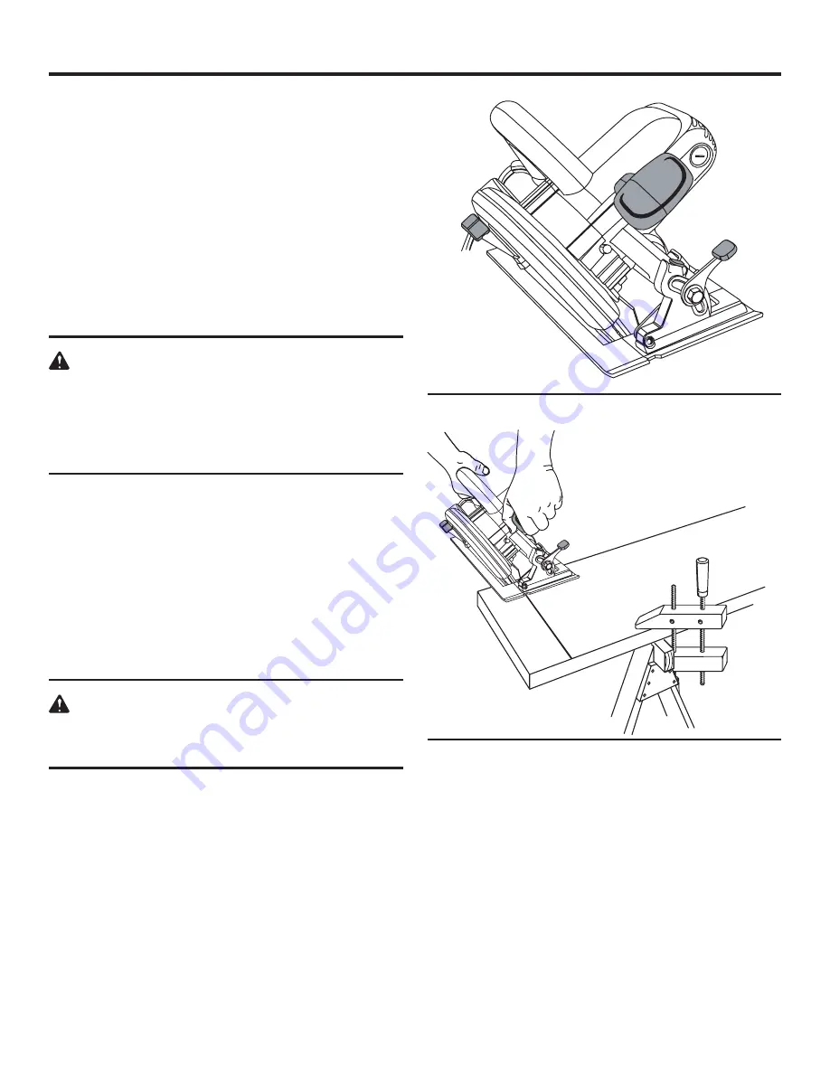
BEVEL CUTTING

See Figures 17 and 18.

To make the best possible cut, follow these helpful hints.

  Align the line of cut with the inner blade guide notch on 

the base when making 45

°

 bevel cuts.

  Make  a  trial  cut  in  scrap  material  along  a  guideline  to 

determine how much you should offset the guideline on 
the cutting material.

  Adjust the angle of the cut to any desired setting between 

zero and 51.5

°

. Refer to "TO ADJUST BEVEL SETTING" 

next.


NOTE:

 Pull the adjustment lever all the way up to set the 

angle at 51.5

°

.

WARNING:

The tool should never be connected to a power 
supply  when  you  are  assembling  parts,  making 
adjustments, cleaning, performing maintenance, or 
when the tool is not in use. Disconnecting the tool 
will prevent accidental starting that could cause 
serious injury.

TO ADJUST BEVEL SETTING

See Figure 17.

Follow these directions to adjust the bevel setting.

  Unplug the saw.

  Pull the bevel adjustment lever upward until the motor 

housing moves freely.

  Raise motor housing end of saw until you reach the de-

sired angle setting on bevel scale.

  Press downward on the bevel adjustment lever until the 

motor housing is securely locked in place.

WARNING:

Attempting a bevel cut without having the bevel 
adjustment  lever  securely  locked  in  place  can 
result in serious injury.

TO BEVEL CUT

See Figure 18.

Follow these directions to bevel cut.

  Hold the saw firmly with both hands as shown.

  Rest the front edge of the base on the workpiece.

  Start the saw and let the blade reach full speed.

  Guide the saw into the workpiece and make the cut.

  Release  the  trigger  and  allow  the  blade  to  come  to  a 

complete stop.

  Lift the saw from the workpiece.

OPERATION

Fig. 18

Fig. 17

Summary of Contents for R3200

Page 1: ...n properly cared for it will give you years of rugged trouble free performance WARNING To reduce the risk of injury the user must read and understand the operator s manual before using this product Th...

Page 2: ...derstand completely the operator s manual Pay close attention to the safety rules including Dangers Warnings and Cautions If you use your product properly and only as intended you will enjoy years of...

Page 3: ...tch or plugging in tools that have the switch on invites accidents Remove adjusting keys or wrenches before turning the tool on A wrench or a key that is left attached to a rotat ing part of the tool...

Page 4: ...ool by insulated gripping surfaces when performing an operation where the cutting tool may contact hidden wiring or its own cord Contact with a live wire will also make exposed metal parts of the tool...

Page 5: ...ing and KICKBACK Blade depth and bevel adjusting locking levers must be tight and secure before making cut If blade adjustment shifts while cutting it may cause binding and KICKBACK Use extra caution...

Page 6: ...g Current Type of current Direct Current Type or a characteristic of current no No Load Speed Rotational speed at no load Class II Construction Double insulated construction min Per Minute Revolutions...

Page 7: ...in 57 mm Cutting Depth at 45 1 3 4 in 45 mm Cutting Depth at 51 5 1 5 8 in 41 mm Input 120 Volts 60 Hz AC only 15 Amps No Load Speed 5800 min Net Weight 10 6 lbs 4 8 kg EXTENSION CORDS When using a p...

Page 8: ...les POWER CORD The 12 foot cord has a built in cord wrap LIGHTED PLUG The lighted plug helps to easily identify live tools UNPACKING INSTRUCTIONS When unpacking the circular saw Carefully remove the t...

Page 9: ...9 Fig 1 FEATURES POWER CORD RIP GUIDE HANDLE FULL LENGTH KERF INDICATOR DUST CHUTE SPINDLE LOCK SWITCH FRONT HANDLE LIGHTED PLUG...

Page 10: ...r to come to a complete stop before engaging spindle lock Depress spindle lock button Remove blade screw by turning it counterclockwise with the wrench Remove outer washer D washer and spring washer W...

Page 11: ...mage to the spindle or spindle lock always allow motor to come to a complete stop before engaging spindle lock Depress spindle lock button Remove blade screw by turning it counterclockwise with the wr...

Page 12: ...de guard does not cover blade on the underside of work Since blade is exposed on underside of work keep hands and fingers away from cutting area Any part of your body coming in contact with moving bla...

Page 13: ...tly or misusing the tool To lessen the chance of kickback follow these safety prac tices Keep the blade at the correct depth setting The depth setting should not exceed 1 4 in 6 35 mm below the materi...

Page 14: ...ometo a complete stop Do not remove the saw from the workpiece while the blade is moving ADJUSTING BLADE DEPTH See Figure 10 Always keep correct blade depth setting The correct blade depth setting for...

Page 15: ...e workpiece while making a cut Support the workpiece so that the cut is always on your right Support the workpiece near the cut Clamp the workpiece securely so that the workpiece will not move during...

Page 16: ...d offset the guideline TO RIP CUT See Figures 15 and 16 Use a guide when making long or wide rip cuts with the saw NOTE You may also use the rip guide that is provided with the saw To install the rip...

Page 17: ...tal starting that could cause serious injury TO ADJUST BEVEL SETTING See Figure 17 Follow these directions to adjust the bevel setting Unplug the saw Pull the bevel adjustment lever upward until the m...

Page 18: ...let the blade reach full speed Guide the saw into the workpiece and make the cut WARNING Always cut in a forward direction when pocket cutting Cutting in the reverse direction could cause the saw to...

Page 19: ...P Follow these directions to check the positive 0 bevel stop Unplug the saw Place the saw in an upside down position on a work bench Move the lower blade guard out of the way so that the saw blade is...

Page 20: ...bricant for the life of the tool under normal operating conditions Therefore no further lubrication is required MAINTENANCE WARNING When servicing use only identical RIDGID replace ment parts Use of a...

Page 21: ...www ridgid com When requesting warranty service you must present the original dated sales receipt The authorized service center will re pair any faulty workmanship and either repair or replace any par...

Page 22: ...ation of the authorized service center nearest you please call 1 866 539 1710 or visit us online at www ridgid com The model number of this tool is found on a plate attached to the motor housing Pleas...

Reviews: