RIDGID JP0600 Owner'S Manual Download Page 8

8

Motor Specifications and Electrical Requirements (continued)

Do not modify the plug provided. If it will not fit the outlet,
have the proper outlet installed by a qualified electrician.

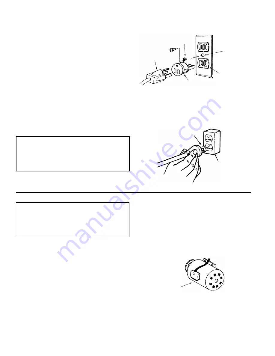
A temporary adapter may be used to connect this plug to
a 2-pole outlet, as shown. This temporary adapter should
be used only until a properly grounded outlet can be
installed by a qualified electrician. The green colored
rigid ear, lug and the like, extension from the adapter
must be connected to a permanent ground such as a
properly grounded outlet box.

Improper connection of the equipment grounding con-
ductor can result in a risk of electric shock. The conduc-
tor with insulation having an outer surface that is green
with or without yellow stripes is the equipment grounding
conductor. If repair or replacement of the electric cord or
plug is necessary, do not connect the equipment-ground-
ing conductor to a live terminal.

If the grounding instructions are not completely under-
stood, or if you are in doubt as to whether the tool is prop-
erly grounded check with a qualified electrician or service
personnel.

WARNING: If not properly grounded, this tool can
cause an electrical shock, particularly when used
in damp locations, in proximity to plumbing, or out
of doors. If an electrical shock occurs there is the
potential of a secondary hazard, such as your
hands contacting the knives.

110-120 Volt, 60 Hz. Tool Connections

NOTE: The adapter illustrated is for use only if you already
have a properly grounded 2-prong outlet.

NOTE: In Canada the use of a temporary adapter is not
permitted by the Canadian electrical code.

220-240 Volt, 60 Hz. Tool Connections

Changing Motor Voltage

WARNING: If not properly grounded, this tool can
cause an electrical shock, particularly when used
in damp locations, in proximity to plumbing, or out
of doors. If an electrical shock occurs there is the
potential of a secondary hazard, such as your
hands contacting the knives.

NOTE: The jointer is prewired at the factory for 120V
operation. Use the following procedure to change motor
voltage. To change to 240V application an additional wire
nut is supplied from the factory. This part is included in
the loose parts.
1. Open the motor junction box cover located on the side

of the motor. 

2. Cut off the 120 volt power cord plug and replace it with

a (3 blade) 240 volt 15 amp U.L. listed plug. (See illus-
tration of 240V plug & receptacle.) Connect the power
cord white and black leads, respectively, to the “hot”
plug blade terminals and connect the power cord
green grounding wire to the plug ground prong termi-
nal.

3. Remove and discard the electrical tape from the wire

nuts. Remove wire nuts.

4. Reconnect the leads as shown in the “Wiring Diagram”

section at the rear of manual.

5. Reinstall the wire nuts and wrap with two layers of new

U.L. listed electrical tape per wire nut.

6. Recheck your wiring to the wiring diagrams. Do this so

you can be sure that the wiring is correct.

7. Reinstall the junction box cover.

3-Prong

Adapter

2-Prong

Outlet

Make Sure This

Is Connected

Ground

Plug

Green

to a Known

Grounding Lug

Grounding

Prong

Grounded

Outlet Box

Junction

Box Cover

Summary of Contents for JP0600

Page 1: ...2 1 5 6 0 18 VVHPEO 2SHUDWLRQ 5HSDLU 3DUWV RU RXU 6DIHW 5HDG DOO LQVWUXFWLRQV FDUHIXOO 48 67 216 25 200 176 5 ZZZ ULGJLGZRRGZRUNLQJ FRP Part No SP6173 Printed in Taiwan 3 2 17 5 3 1 5...

Page 2: ...binet 16 Assemble Bed to Stand 16 Mounting On Off Switch 17 Attach Front of Cabinet and Dust Chute 17 Assemble Fence To Bed 18 Install Cutter Head Guard 18 Cutter Head Guard Functional Check 18 Adjust...

Page 3: ...hown on the sliding fence guard behind the center of the fence 4 Thrown workpiece chips and cutter blade pieces The jointer planer can throw the workpiece workpiece chips or pieces of loose or broken...

Page 4: ...ng or jointing it To reduce the risk of injury from electrical shock make sure your fingers do not touch the plug s metal prongs when plugging in or unplugging the jointer planer Turn off and unplug t...

Page 5: ...nter planer into a power outlet Dress for safety Any power tool can throw foreign objects into the eyes This can result in permanent eye damage Always wear safety goggles not glasses complying with AN...

Page 6: ...ry of Terms for Woodworking Bed The combination of infeed and outfeed table surfaces which support the workpiece during a cutting operation Bevel Chamfer Removing wood along the edge of a board to mak...

Page 7: ...Connections DANGER To reduce the risk of electrocution 1 Use only identical replacement parts when ser vicing Servicing should be performed by a qualified service technician 2 Do not use in rain or wh...

Page 8: ...u already have a properly grounded 2 prong outlet NOTE In Canada the use of a temporary adapter is not permitted by the Canadian electrical code 220 240 Volt 60 Hz Tool Connections Changing Motor Volt...

Page 9: ...ne voltages should not be more than 10 above or below the nameplate voltage For heavy loads however the voltage at motor terminals must equal the voltage specified for your model c Improper or dull jo...

Page 10: ...vent such as mineral spirits Water will rust the surfaces Do Not use water soapy water or water based cleaners CAUTION Use solvents according to the instruc tions on their package Use only in well ven...

Page 11: ...11 Loose Parts E D A B M N T L R S U G H J K C F Q P...

Page 12: ...3mm Hex L Wrench 1 Rod Knife Gauge 1 Gauge Knife 2 Retaining Ring 4 1 4 Lockwasher 3 3 8 Nut Hex 4 5 16 18 5 16 18 x 3 4 Screw Pan Head 3 1 4 20 x 1 2 Wrench 8mm 10mm 1 Wrench 12mm 14mm 1 3 8 16 Wire...

Page 13: ...three lowest holes on each side of the cabi net rear NOTE The front of the cabinet will be attached later Install the Leveling Feet From the loose parts bag find the following 4 Leveling Feet 4 Nut He...

Page 14: ...Motor Mount Plate 2 Motor Mount Side 2 Attach the motor mount sides to the cabinet top as shown 3 Attach the motor mount plate to the motor mount sides and cabinet top Cabinet Top Motor Mount Plate Mo...

Page 15: ...bly w Switch 4 Hex Bolt 5 16 18 x 3 4 8 Flat Washers 5 16 4 Hex Nuts 5 16 18 2 Position the motor on the motor mount plate as shown 3 Secure the motor with the hex head bolts as shown Finger tighten n...

Page 16: ...ead 1 4 20 x 1 2 1 Washer 1 4 1 V Belt WARNING This tool is heavy To reduce the risk of back injury get help whenever you have to lift the tool 2 Set the bed on top of the stand Carefully line up the...

Page 17: ...Front of Cabinet and Sawdust Chute 1 Locate the following 1 Cabinet Front 1 Sawdust Chute 9 Machine Screws with Washer Heads 4 Wing Screw 1 4 20 x 5 8 2 Position the cabinet front as shown 3 Secure w...

Page 18: ...ob 1 turn counterclockwise looking down through the hole in the infeed table 3 Line the slot in the guard post with the pin in the knob Slide the post through table and over pin in the knob 4 Reinstal...

Page 19: ...w in the bottom of the guard post Attaching Pulley Guard 1 From among the loose parts find the following 4 Machine Screw w Washer Head 3 16 24 x 3 8 1 Pulley Guard 2 Attach the upper pulley guard to t...

Page 20: ...ove across table front to back This is done to achieve full width of cut or to use a different sharper part of blade 4 90 and 45 Fence Stops When adjusted properly these stops provide a method for qui...

Page 21: ...rt key into switch To turn the tool On insert finger under the switch lever and pull end of lever out To turn the tool Off push the lever in Never leave the tool unattended until it has come to a comp...

Page 22: ...knives Lock the fence in this position 4 Remove cutter head guard 5 Place the gage on the cutter head as shown The pad of the gauge should be flush with the blade If not adjust the blade as follows B...

Page 23: ...tent Look under Sharpening Services in the Yellow Pages of your telephone directory NOTE The knives may have a second very small ground surface very close to the sharpened edge of the blade Hone only...

Page 24: ...r end readjust knife per Cutter Knife Adjust ment Replacement procedure 4 After the outfeed table has been set at the correct height lock in place using wing screw table locks It should not be changed...

Page 25: ...table and check fence while locked at 90 position To ensure accuracy and repeatability of the stops the bottom of the outfeed side of the fence should rest firmly against the outfeed table and agains...

Page 26: ...ers Three Inch Rule 3 Generally if your hands are closer than three inches to the blade as you feed the wood use push blocks This gives extra protection to your hands by placing the push blocks betwee...

Page 27: ...cut Plan your cut Small or thin workpieces can kickback when they tip over on the tables or into the cutter head To reduce the risk of head contact or workpiece kickback Never joint plane or bevel wo...

Page 28: ...one cut Cut in 1 8 depth increments until your full depth is acquired Feeding the Workpiece Hold the board firmly down on both tables and against the fence Keep fingers close together Feed the board a...

Page 29: ...edge straight smooth and square to the wood face which is against the fence To ensure a square cut the workpiece face must be held flat against the fence throughout the entire cut Beveling Chamfering...

Page 30: ...Workpieces To reduce the risk of injury from slips or kickbacks use extra supports tables saw horses etc at both infeed and outfeed ends if your workpiece if hard to hold down to the table Using the H...

Page 31: ...stop before adjusting fence When you are not cutting at full width of cut the fence can be moved across the jointer planer to take full advantage of the sharpness of the blades When blades are new or...

Page 32: ...an Authorized Service Center Disregarding this may void your tools warranty NOTE The speed of this motor cannot be regulated or changed Motors used on woodworking tools are particularly sus ceptible t...

Page 33: ...33 Wiring Diagram White White Black Black Motor Junction Box 1 3 5 1 4 8 3 5 2 2 4 8 120V Power Cord 240V Power Cord Wire Nut Wire Nut Green Green 120V Wiring 240V Wiring Motor Junction Box...

Page 34: ...laned sur face Kickbacks 1 One blade set higher than other 2 Feeding wood too fast 3 Cutting blades are set too high above outfeed table or they are not leveled with outfeed table 1 Readjust blades se...

Page 35: ...power company Motor starts slowly or fails to come to full speed 1 Windings burned out or open 2 Drive belt tension too high 3 Defective start capacitor 1 Have motor repaired or replaced 2 Adjust belt...

Page 36: ...inter Planer Model No JP06000 RIDGID parts are available on line at www ridgidparts com Figure 1 1 2 3 10 5 6 7 8 17 11 12 13 14 15 16 20 9 4 18 19 21 22 23 13 10 11 9 24 25 26 27 28 29 30 31 32 33 35...

Page 37: ...n Hd M5 x 0 8 10 Gib Screw Set 1 4 20 x 1 Nut Hex 1 4 20 Screw Elevation Washer Brass Clamp Screw Set 1 4 20 x 3 8 Collar Handwheel Washer 17 64 x 5 8 x 1 32 Screw Pan Hd 1 4 20 x 1 2 Lockwasher 8mm S...

Page 38: ...Parts Parts List for RIDGID 6 1 8 Jointer Planer Model No JP06000 RIDGID parts are available on line at www ridgidparts com Figure 2 1 2 3 5 6 7 8 9 10 11 12 17 18 19 20 21 22 23 24 25 26 27 14 15 16...

Page 39: ...26643 Slide Fence Screw Set Dog Point 1 4 20 x 1 2 Knob Rod Knob Knob Nut Nut Hex 3 8 16 Washer 3 8 x 3 4 x 3 32 Ring Retaining 6mm Rod Bevel Lock Screw Pan Hd 1 4 20 x 1 2 Washer 17 64 5 8 x 1 32 Gua...

Page 40: ...Parts Parts List for RIDGID 6 1 8 Jointer Planer Model No JP06000 RIDGID parts are available on line at www ridgidparts com Figure 3 1 2 3 4 5 6 7 8 9 12 14 17 18 19 15 16 13 3 21 10 11 20 3 3 3 3 3...

Page 41: ...11 826522 826658 826639 826645 826659 826647 826680 803835 1 Chute Dust Screw Wing 1 4 20 x 5 8 Screw Pan Cr Serr 3 16 24 x 3 8 Panel Left Side Panel Top Guard Pulley Stiffener Rear Lockwasher 10mm St...

Page 42: ...u purchased your jointer 1 2 3 4 5 6 7 8 9 10 11 12 13 10 11 14 8 Key No Part No Description 1 2 3 4 5 6 7 824886 824885 AC8600 824883 818654 7 820722 5 824881 1 Screw 1 4 28 x 7mm Wedge Blade Spring...

Page 43: ...2 6 8 9 10 11 15 Key No Part No Description 1 2 3 4 5 6 7 8 9 826122 826123 826395 826653 824914 Key Switch Switch Locking Screw Ty AB M4 x 1 6 18 Bezel Switch Screw Pan Hd 8 32 x 3 8 Lockwasher 8 Pla...

Page 44: ...lec tric Co Warranted products will be repaired or replaced at our option at no charge to you and returned to you via prepaid transportation Such replacement or repair is the exclusive rem edy availab...

Reviews: