background image

Ridder Drive Systems


T

 +31 (0)341 416 854       

F

 +31 (0)341 416 611      

 www.ridder.com

22

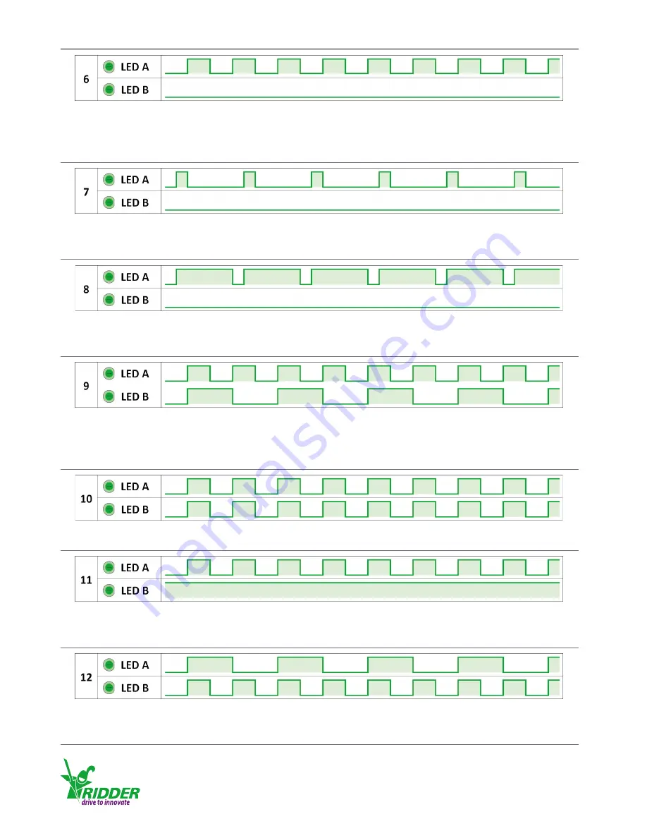
Blink code / Meaning


● Operating mode: A mechanical overload has been detected. The RLD80 can no longer be 

operated in the rotational direction where the overload has occurred. However, you can 

reverse the rotational direction of the RLD80.


● Operating mode: 10 minor mechanical overloads have been detected. This has caused the 

RLD80 to stop. Disconnect the supply voltage to reset the RLD80.


● Operating mode: 10 major mechanical overloads have been detected. This has caused the 

RLD80 to stop. Disconnect the supply voltage to reset the RLD80.


● Operating mode: End positions A and B have not been taught in yet.


● Teach-in mode: End position B (the RLD80 is in this end position) has been programmed; end 

position A has not yet been programmed.


● Teach-in mode: End positions A and B have not been taught in yet.


● Teach-in mode: End position B (the RLD80 is not in this end position) has been programmed; 

end position A has not yet been programmed.


● Teach-in mode: End position A (the RLD80 is in this end position) has been programmed; end 

position B has not yet been programmed.

Summary of Contents for LogicDrive RLD80

Page 1: ...r LogicDrive RLD80 265100EN 2017 07 V04 Ridder Drive Systems Lorentzstraat 36 38 3846 AX Harderwijk P O Box 360 3840 AJ Harderwijk The Netherlands T 31 0 341 416 854 F 31 0 341 416 611 I www ridder co...

Page 2: ...buckle to the winch belt 9 3 6 Mounting the sprocket 9 4 1 Connection and operation abbreviations 10 4 2 Connecting the control components and switch materials and cable lengths 10 4 3 LogicDrive RLD...

Page 3: ...ically adjustable from 0 25 to 100 revolutions of the drive shaft The integrated motor control unit of the RLD80 protects the drive unit against overloading and adjusts it to a taught in position in t...

Page 4: ...110 mm x 150 mm x 230 mm Weight 9 6 12 1 kg Electrical Supply voltage 24 V DC 10 Maximum current 2 A Power 48 W Alarm contact 24 V AC DC 1 A Protection Mechanical and thermal overload Control Control...

Page 5: ...r single winch belt 70 mm for double winch belt see also 3 4 Winding capacity of drum 2000 mm with single winch belt 1200 mm with double winch belt Graph lines 1 RLD80 winch belt pull force per winch...

Page 6: ...when installing the LogicDrive RLD80 3 1 LogicDrive RLD80 mounting positions 2 6 LogicDrive RLD80 packaging contents Each LogicDrive RLD80 unit is packaged in a box together with its accessories The f...

Page 7: ...he drilling template to mark the holes onto the wall or structure If you do not wish to use the template mark the holes as shown opposite 4a Mounting the unit to a wall blind holes Drill holes for wed...

Page 8: ...RLD80 as follows 3 4 Pre winding the winch belt onto the belt drum To safely use the belt drum and winch belt of the LogicDrive RLD80 it is necessary to first pre wind the belt onto the drum Belt drum...

Page 9: ...416 854 F 31 0 341 416 611 I www ridder com 9 3 5 Mounting the triangle and buckle to the winch belt Mount the triangle and buckle to the winch belt as follows 3 6 Mounting the sprocket Mount the spr...

Page 10: ...ble 4 14 AL Alarm signal from LogicDrive 5 15 AL Return wire of alarm signal from LogicDrive 6 16 Sgn 0 10 V DC control signal to LogicDrive 7 17 Gnd Return wire of control signal to LogicDrive 8 18 S...

Page 11: ...gicDrive RLD80 It also shows where the operating elements are located on the control board X1 and the motor board X2 4 3 LogicDrive RLD80 wiring diagram and operating elements Always use separate cabl...

Page 12: ...icDrive RLD80 rotational direction and the end and emergency positions The figure below shows the control buttons DIR A and DIR B along with the corresponding rotational direction of A and B The figur...

Page 13: ...e minimum movement between end positions A and B is 90 revolution of the drive shaft Emergency position To use the emergency position C the minimum control voltage must be higher than 1 V The emergenc...

Page 14: ...trol button DIR A then press the programming button PROG and then release both buttons Pulse operation can be stopped at any time by pressing one of the control buttons If end position A has been prog...

Page 15: ...V A larger difference is recommended to control the RLD80 more accurately To teach in an emergency position the minimum value of the control signal must be 1 V If the control signal is lost the RLD80...

Page 16: ...ture 1 Set the DIP switch S1 to Teach in mode 2 Set the control unit of the RLD80 such as the Ridder LogicControl RLC101 to Auto mode 3 From the climate controller send the desired control signal 0 10...

Page 17: ...utton DIR B to set the desired end position B If necessary use button DIR A to adjust end position B 8 To save the selected end position B first press and hold down the programming button PROG and the...

Page 18: ...n the LogicDrive RLD80 Programming an emergency position u Description Picture 1 Set DIP switch S1 to Teach in mode 2 Use button DIR A or DIR B to set the desired emergency position C Pulse operation...

Page 19: ...R A Release both buttons once the corresponding LED A starts blinking faster Remarks End position A can be erased while in any position The blink code for LED B may be different 2 B To erase end posit...

Page 20: ...A and LED B will blink according to a certain blink code see 8 1 2 To erase emergency position C press the programming button PROG Release the button once both LEDs i e LED A and LED B turn off briefl...

Page 21: ...0 10 V DC control signal Note Since the alarm contact always switches in unison with LED B the alarm contact will switch according to the blink code of LED B while the RLD80 is in teach in mode 8 1 Lo...

Page 22: ...Operating mode 10 major mechanical overloads have been detected This has caused the RLD80 to stop Disconnect the supply voltage to reset the RLD80 Operating mode End positions A and B have not been ta...

Page 23: ...the RLD80 is in this end position has been programmed end position A has also been programmed Teach in mode End position A the RLD80 is in this end position has been programmed end position B has als...

Page 24: ...he RLD80 to cancel the lock function You will then be able to operate the RLD80 in the rotational direction that was previously locked Cause 5 The RLD80 has experienced multiple overloads blink code 7...

Page 25: ...been connected making the 0 10 V DC input susceptible to interference from external signal sources Solution 2 Connect the shield of the control cable in the control box Cause 3 The control cable is no...

Page 26: ...gicControl RLC101 control unit for 2 LogicDrives RLD80 587200 RLP200 24V DC Ridder LogicPower RLP200 emergency power supply for 1 or 2 LogicDrives RLD80 requires LogicControl unit 507220 MOUNTING SET...

Page 27: ...mportance The following list explains what they mean 12 1 Meaning of warnings in this product manual A suggestion to perform an action more efficiently May result in damage or problems if an action is...

Page 28: ...www ridder com...

Reviews: