background image

4.Replacement and Adjustment 

93 

15. 

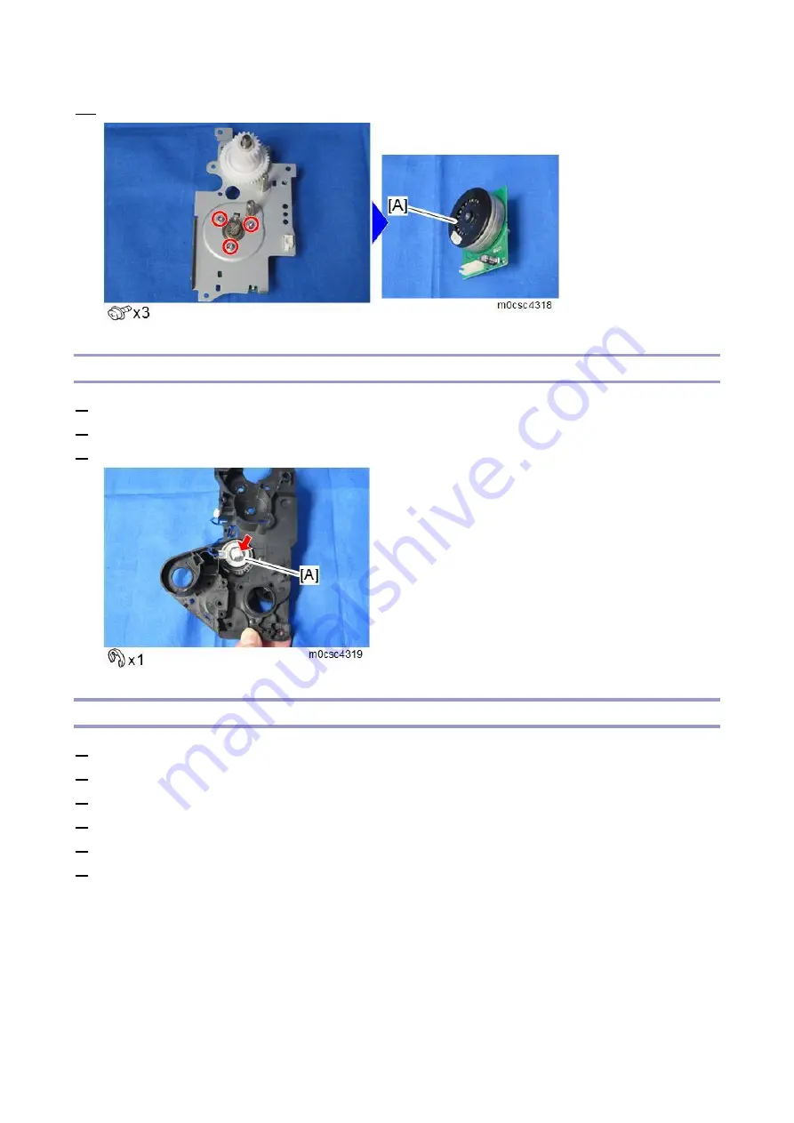
Remove the fusing motor (M4) [A]. 


Registration Clutch (CL2) 

1. 

Remove the left cover. (

Left Cover

) 

2. 

Remove the fusing motor. (

Fusing Motor (M4)

) 

3. 

Remove the registration clutch (CL2) [A]. 


Paper Feed Roller 

1. 

Remove all AIO cartridges. (

AIO Cartridge

) 

2. 

Remove the waste toner bottle. (

Waste Toner Bottle

) 

3. 

Remove the left cover. (

Left Cover

) 

4. 

Remove the paper feed clutch. (

Paper Feed Clutch (CL1)

) 

5. 

Close the top cover and the front cover. 

6. 

Pull out the paper tray. 

Summary of Contents for M C250FW

Page 1: ...P C300W C301W M C250FWB C250FW Machine Code M0CS M0CW M0CX M0CZ Field Service Manual Ver 1 0 Latest Release July 2019 Initial Release July 2019 c 2019 Ricoh Co Ltd ...

Page 2: ......

Page 3: ...riginals loss of valuable data and to prevent damage to the machine This information provides tips and advice about how to best service the machine General Safety Instructions For your safety please read this manual carefully before you use this product Keep this manual handy for future reference Safety Information Always obey the following safety precautions when using this product Safety During ...

Page 4: ...Do not use flammable sprays or solvent in the vicinity of the machine Also avoid placing these items in the vicinity of the machine Doing so could result in fire or electric shock 11 To avoid fire or explosion never use an organic cleaner near any part that generates heat 12 Clean the floor completely after accidental spillage of silicone oil or other materials to prevent slippery surfaces that co...

Page 5: ...an health Therefore locate the machine in a large well ventilated room that has an air turnover rate of more than 50m3 hr person 3 Toner and developer are non toxic but if you get either of them in your eyes by accident it may cause temporary eye discomfort Try to remove with eye drops or flush with water as first aid If unsuccessful get medical attention Observance of Electrical Safety Standards ...

Page 6: ... and AIO unit out of the reach of children Always store fresh toner supplies or empty bottles or cartridges in a cool dry location that is not exposed to direct sunlight Do not use a vacuum cleaner to remove spilled toner including used toner Vacuumed toner may cause a fire or explosion due to sparks or electrical contact inside the cleaner However it is possible to use a cleaner designed to be du...

Page 7: ... this manual may result in hazardous radiation exposure WARNING FOR LASER UNIT WARNING Turn off the main switch before attempting any of the procedures in the Laser Unit section Laser beams can seriously damage your eyes Safety Instructions for the Color Controller Fuse The color controller uses a double pole fuse If this fuse blows be sure to replace it with an identical fuse Batteries Always rep...

Page 8: ......

Page 9: ...ose symbols and abbreviations are as follows Symbol What it means Clip ring Screw Connector Clamp E ring Flexible flat cable FFC Timing belt SEF Short edge feed LEF Long edge feed K Black C Cyan M Magenta Y Yellow B W BW Black and White FC Full color A Short edge feed SEF B Long edge feed LEF 保存 ...

Page 10: ... States and or other countries PCL is a registered trademark of Hewlett Packard Company QR Code is a registered trademark of DENSO WAVE INCORPORATED in Japan and in other countries Red Hat is a registered trademark of Red Hat Inc Wi Fi and Wi Fi Direct are registered trademarks of Wi Fi Alliance The proper names of Internet Explorer 9 10 and 11 are as follows Windows Internet Explorer 9 Internet E...

Page 11: ... Microsoft Windows Server 2012 Standard The product names of Windows Server 2012 R2 are as follows Microsoft Windows Server 2012 R2 Foundation Microsoft Windows Server 2012 R2 Essentials Microsoft Windows Server 2012 R2 Standard The product names of Windows Server 2016 are as follows Microsoft Windows Server 2016 Standard Microsoft Windows Server 2016 Essentials Other product names used herein are...

Page 12: ......

Page 13: ...ce 17 Preventive Maintenance 17 Cleaning Points 18 Image Quality Standards 23 Paper Transfer Quality Standards 24 4 Replacement and Adjustment 25 General Cautions 25 Special Tools 26 Exterior Covers 27 Rear Cover 27 Operation Panel 29 Right Cover 31 Left Cover 31 Front Cover Unit 32 ADF Scanner Unit MF Model Only 34 ADF Scanner Assembly 34 Extension Tray Original Tray 39 ADF Front Cover 40 ADF Rea...

Page 14: ...S9 69 Waste Toner Bottle Set Sensor S10 71 Image Fusing 73 Fusing Unit 73 Fusing Upper Cover 74 Fusing Lower Cover 74 Fusing Entrance Sensor S2 75 Fusing Thermostat TH1 75 Fusing NC Sensor S1 76 Pressure Roller Thermistor End TH4 76 Pressure Roller Thermistor Center TH3 78 Fusing Sleeve Belt Unit 79 Pressure Roller 82 Fusing Thermopile TH2 83 Paper Feed and Transfer 84 Paper Transfer Unit 84 Trans...

Page 15: ...S7 114 Fusing Thermopile Anti condensation Fan FAN4 114 Interlock Switches SW1 SW2 SW3 114 Fusing Fan FAN2 115 LSU Fan FAN1 116 PSU Cooling Fan FAN3 116 ID Chip Board PCB6 117 PSU PCB4 121 OPU PCB7 125 5 System Maintenance 127 SP Mode Tables Printer Model 127 Overview 127 Display Info 127 Engine Maintenance 128 Factory Default 140 CTL Maintenance 140 System Maintenance 140 Test Pattern 140 Remote ...

Page 16: ...ng 192 Service Call 192 Service Call Conditions 192 SC 1xx Other Error 192 SC 2xx Image Writing 193 SC 3xx Around the Drum 196 SC 4xx Image Transfer 197 SC 5xx Paper Feed and Fusing 200 SC 6xx Device Communication 215 SC 9XX Other Error 220 Fax Error Code MF Model Only 222 Fax Error Code Structure 222 Fax Error Code Table 223 Jam Detection 225 Jam Detection 225 Transport Path Length 226 Paper Deli...

Page 17: ... Cleaning Message Does Not Disappear 247 7 Detailed Descriptions 249 Guidance for Those Who are Familiar with Predecessor Products 249 Machine Overview 251 Component Layout 251 Paper Path 252 Drive Layout 252 Electrical Component 253 ADF MF Model Only 258 Overview 258 Mechanism 258 Scanner MF Model Only 260 Overview 260 Mechanism 260 Laser Exposure 261 Overview 261 Mechanism 261 MUSIC Mirror Unit ...

Page 18: ...6 Image Fusing 276 Overview 276 Mechanism 276 Paper Feed 280 Overview 280 Mechanism 280 Paper Exit and Duplex 283 Overview 283 Mechanism 284 Boards 285 Block Diagram 285 Board Outline 286 ...

Page 19: ...1 Product Information 7 1 Product Information Specifications See Appendices for the following information General Specifications Supported Paper Sizes ...

Page 20: ...r 4 line LCD Not Supported For NA EU AA M 250FWB M0CX BW FC 25ppm A4 LT 4 in 1 4 3 inch touch panel Supported For NA EU AA TWN CHN M 250FW M0CZ BW FC 25ppm A4 LT 4 in 1 4 3 inch touch panel Supported For NA EU AA Note Supported AIO Black Color AIO P C300W P C301W M 250FWB M 250FW High Yield AIO 7 2K 6 6K Short Yield AIO 2 3K 2 3K Optional Equipment No Name Machine Code Paper Capacity 80 g m2 Remar...

Page 21: ...eas directly exposed to cool air from an air conditioner Areas directly exposed to heat from a heater 6 Do not put the machine in areas that get exposed to corrosive gases ammonia etc 7 Do not install the machine at locations over 2 500 m 8 202 ft above sea level For Chinese model 2 000 m 6 561 ft 8 Put the machine on a sturdy level base Inclination on any side must be no more than 3 mm 9 Do not p...

Page 22: ... source with these clearances Printer Model A Left side Over 20 cm 7 9 B Right side Over 10 cm 4 0 C Front Over 70 cm 27 6 D Rear Over 20 cm 7 9 E Top Over 33 cm 13 0 MF Model A Left side Over 20 cm 7 9 B Right side Over 10 cm 4 0 C Front Over 70 cm 27 6 D Rear Over 20 cm 7 9 ...

Page 23: ...n the outlet Avoid multi wiring Make sure the machine is grounded Input voltage level 120 V to 127 V 60 Hz Less than 11 A for North America 220 V to 240 V 50 Hz 60 Hz Less than 6 A for Europe Asia 110 V 60 Hz Less than 12 A for Taiwan Permitted voltage fluctuation 10 Do not set anything on the power cord ...

Page 24: ...2 Installation 12 Installation Procedure Refer to the Quick Installation Guide for details about installing the machine ...

Page 25: ...TP Proxy Use MF model SP menu Remote Remote Service Use Proxy Proxy server IP address Printer model SP menu Remote Remote Service HTTP Proxy Host MF model SP menu Remote Remote Service Proxy Host Proxy server Port number Printer model SP menu Remote Remote Service HTTP Proxy Port MF model SP menu Remote Remote Service Proxy PortNumber Proxy User ID Printer model SP menu Remote Remote Service HTTP ...

Page 26: ... SP menu Engine Maintenance Serial No MF model SP menu Engine SN SP Serial No 4 Input the request number which you have obtained from the Remote Center GUI and then enter OK Printer model Remote Remote Service Instl ID MF model Remote Remote Service Letter Number 5 Confirm the Request Number Printer model Remote Remote Service Instl Reference MF model Remote Remote Service Confirm Execute 6 Check ...

Page 27: ...ocessing Please wait 10 Select the Function Flag and check that it is Enable Printer model Remote Remote Service Function Flag MF model Remote Remote Service Function Flag When the registration is completed in step 9 the Function Flag is changed to Enable 11 Then turn the machine OFF and ON After Settings The first manual call after settings is considered as a test call Be sure to execute the test...

Page 28: ...pdate certification failed because mainframe was in use Check the machine condition If the machine is in use try again later Error Caused by Response from GW URL Code Meaning Solution Workaround 2387 Not supported at the Service Center 2389 Database out of service 2390 Program out of service 2391 Two registrations for the same mainframe Check the registration condition of the machine 2392 Paramete...

Page 29: ...3 Preventive Maintenance 17 3 Preventive Maintenance Preventive Maintenance See Appendices for the following information Preventive Maintenance ...

Page 30: ...ce to the left Exposure Glass Only MF Model 1 Open the ADF unit 2 Clean the parts indicated by arrows with a soft damp cloth and then wipe the same parts with a dry cloth to remove any remaining moisture ADF Exposure Glass Only MF Model 1 Open the ADF unit 2 Clean the parts indicated by arrows with a soft damp cloth and then wipe the same parts with a dry ...

Page 31: ...4 Open the ADF cover 5 Clean the indicated parts with a soft damp cloth and then wipe the same parts with a dry cloth to remove any remaining moisture Registration Roller Do not use volatile chemicals such as benzine or thinner Do not touch the paper transfer roller 1 Open the front cover ...

Page 32: ... cloth Separation Pad Paper Feed Roller 1 Pull out the paper tray and remove the paper in the tray 2 Wipe the separation pad with a soft damp cloth 3 Wipe the paper feed roller with a soft damp cloth and then wipe the same parts with a dry cloth to remove any remaining moisture ...

Page 33: ...o the machine Paper Tray 1 Pull out the paper tray and remove the paper in the tray 2 Wipe the inside of the paper tray with a cloth LD Unit Dust Shield Glass When image defects vertical stripes occur clean if necessary 1 Open the upper cover 2 Clean each dust shield glass with a soft damp cloth and then wipe the same area with a dry cloth ...

Page 34: ...3 Preventive Maintenance 22 to remove any remaining moisture ...

Page 35: ...ification Error Main 0 50 or less Bk Sub 0 60 or less Bk Linearity 0 20 mm 100 mm or less Copy Item Specification Remarks Resolution 100 Enlargement Min 3 6 lines mm or more Reduction Min 3 6 M lines mm or more M Magnification ratio Not applicable when using the ADF Magnification Error Main 1 00 or less Bk Sub 1 10 or less Bk Assured Image Area Leading edge 4 2 mm 1 6 inches Left Right 4 2 mm 1 6 ...

Page 36: ...r less Less than B5 SEF Duplex 1 0 mm 100 mm or less Reference value when using the bypass tray 1 0 mm 50 mm Curling after fusing 10 mm or less In an office environment 20 mm or less In other environments ADF Item Specification Remarks Registration Main Scan 0 2 0 mm Sub Scan 0 1 5 mm When 100 printing Skew Main Scan 1 1 2 2 mm 200 mm Sub Scan 1 0 2 8 mm 200 mm These standards are determined using...

Page 37: ...justment 25 4 Replacement and Adjustment General Cautions Turn off the main power switch and disconnect the power cord After replacement make sure that all removed harnesses are connected again and secured in their clamps ...

Page 38: ...Adjustment 26 Special Tools PC Windows 7 8 1 10 or Windows Server 2008 2008 R2 2012 2012 R2 2016 USB cable C 5Y Color Chart Part number VSST9003 C 5Y Color Chart is used during the adjustment after replacing the back CIS ...

Page 39: ... Exterior Covers Rear Cover Printer Model 1 Remove the rear tray cover A and the interface cover B 2 Remove the rear cover A There are some hooks inside the rear cover Slide upward to release the hooks and then remove the rear cover ...

Page 40: ...nd Adjustment 28 MF Model 1 Remove the rear tray cover A and the interface cover B 2 Remove the rear cover A There are some hooks inside the rear cover Slide upward to release the hooks and then remove the rear cover ...

Page 41: ...4 Replacement and Adjustment 29 Operation Panel 1 Open the top cover A 2 Open the front cover A 3 Remove the connector cover A 4 Remove the operation panel A Printer model ...

Page 42: ...4 Replacement and Adjustment 30 MF model For the MF model only disconnect the FFC A by lifting the operation panel The FFC has a lock mechanism so push the button to unlock it ...

Page 43: ...ent and Adjustment 31 Right Cover 1 Remove the rear cover Rear Cover 2 Remove the operation panel Operation Panel 3 Remove the right cover A Top front screw M3 x 8 others M4 x 10 Left Cover 1 Open the top cover A ...

Page 44: ...k and remove the left cover A Top front screw M3 x 8 others M4 x 10 Front Cover Unit 1 Remove the rear cover Rear Cover 2 Remove the operation panel Operation Panel 3 Remove the right cover Right Cover 4 Remove the transfer unit Paper Transfer Unit 5 Remove the gear unit A x2 ...

Page 45: ...4 Replacement and Adjustment 33 6 Release the belt A and then remove the front cover unit B ...

Page 46: ...The ADF unit and scanner unit are connected by an FFC A so they cannot be separated Replace the ADF unit and scanner unit together as the ADF Scanner Assembly 1 Remove the rear cover Rear Cover 2 Remove the controller box cover A 3 Remove the left stand cover A and right stand cover B ...

Page 47: ... the connector A use a tool such as radio pliers to hold it 6 Press and hold the lock button A and then slide the scanner unit B in the direction of the blue arrow 7 Open the top cover and loosen the fixing screw A Do not remove the fixing screw If the fixing screw is removed with the scanner unit at the rear of the machine the scanner unit may fall ...

Page 48: ...on A close the top cover and then slide the scanner unit B in the direction of the blue arrow 9 Open the top cover and remove the fixing screw A The fixing screw is a plastic screwing rivet Use a pair of small pliers to release the anchor and then pull out halfway ...

Page 49: ...bly adjust the contact image sensor CIS for the front and back Because of differences in each individual ADF scanner assembly go into the SP mode and enter the values on the barcode on the assembly to adjust the difference in the color balance between front and back Be sure to perform this adjustment each time you replace the ADF scanner assembly 1 Check the barcode The barcode values are from the...

Page 50: ...rcode Setting Initial value Range steps Description Backside CIS Red White 0 30 to 30 1 Adjusts the difference in color balance between the front and back for red Backside CIS Green White 0 30 to 30 1 Adjusts the difference in color balance between the front and back for green Backside CIS Blue 0 30 to 30 Adjusts the difference in color balance between ...

Page 51: ...ray White 0 30 to 30 1 Adjusts the difference in color balance between the front and back for gray Extension Tray Original Tray 1 Open the extension tray A bend it slightly to disengage the hooks on the sides and then remove it 2 Open the ADF cover disengage the hooks on the sides of the original tray A and then remove the tray ...

Page 52: ...ont Cover 1 While pressing the ADF release bar A on the back of the scanner unit open the ADF 2 Cover the scanner exposure glass with a mat or cloth to prevent it from being damaged 3 Open the ADF cover and then remove the ADF front cover A ...

Page 53: ...pressing the ADF release bar A on the back of the scanner unit open the ADF 2 Cover the scanner exposure glass with a mat or cloth to prevent it from being damaged 3 Remove the screws on the ADF rear cover 4 Remove the screw on the back of the scanner unit ...

Page 54: ...en remove the ADF rear cover A There are four hooks on the ADF rear cover Be sure to disengage all the hooks when you remove the cover ADF Separation Pad 1 Open the ADF top cover 2 While pressing the parts indicated by red arrows remove the ADF separation pad A ...

Page 55: ...Bend the rib A out slightly and then remove the original feed unit B 3 Remove the ADF feed roller A After the installation make sure that the gears turn properly ADF Pick up Roller 1 Open the ADF top cover 2 Bend the rib A out slightly and then remove the original feed unit B ...

Page 56: ...nd then remove it from the original feed unit Work carefully because the gear contains a spring Transport Roller 1 While pressing the ADF release bar A on the back of the scanner unit open the ADF 2 Cover the scanner exposure glass with a mat or cloth to prevent it from being damaged ...

Page 57: ...Raise the transport roller shaft 5 Remove the ADF front cover ADF Front Cover 6 Remove the ADF rear cover ADF Rear Cover 7 Remove the screws at the front side of the ADF drive unit A 8 Lift the ADF drive unit A slightly and then pull the transport roller shaft B out through the gap ...

Page 58: ...Exposure Glass 1 Remove the ADF front cover ADF Front Cover 2 Remove the ADF rear cover ADF Rear Cover 3 Open the ADF upper cover and then remove the back DF exposure glass A To Remove the Back ADF Exposure Glass 1 Press the hooks A at the sides of the back ADF exposure glass outward insert your fingertips ...

Page 59: ...lacement and Adjustment 47 through the gaps B and then push up the back ADF exposure glass C 2 Check that the hooks have been disengaged and then remove the back ADF exposure glass B 4 Remove the back CIS A ...

Page 60: ...ently push down the rear 2 3 Confirm that the back ADF exposure glass has engaged with the hooks A Adjustment after Replacing the Back CIS After replacing the back CIS only and not the complete ADF scanner assembly adjust the difference in the color balance between front and back as follows If you replaced the ADF scanner assembly see Adjustment after Replacing the ADF Scanner Assembly You cannot ...

Page 61: ...kside CIS Blue White 0 30 to 30 1 Adjusts the difference in color balance between the front and back for blue Backside CIS Gray White 0 30 to 30 1 Adjusts the difference in color balance between the front and back for gray 5 Place C 5Y Color Chart image side up on the ADF and then make a duplex color copy 6 Place C 5Y Color Chart image side down on the ADF and then make a duplex color copy 7 Check...

Page 62: ...is targeted gray Image on the front Image on the back Targeted gray Reddish Greenish Adjustment example a Bluish Red 0 4 4 4 Green 0 4 4 4 Blue 0 4 4 4 Gray 0 4 4 4 Case 2 Adjustment values when the image on the front is reddish Image on the back Image on the front Image on the back Targeted gray Reddish Greenish Bluish Adjustment example b Red 4 0 8 8 Green 4 0 8 0 Blue 4 0 0 8 Gray 4 0 8 0 Case ...

Page 63: ... Image on the back Image on the front Targeted gray Reddish Greenish Bluish Red 4 8 0 0 Green 4 0 8 0 Blue 4 8 8 0 Gray 4 0 8 0 10 After adjustment make a duplex color copy and then confirm that the colors are the same on both sides ...

Page 64: ...e sure to turn off the main power switch and disconnect the power plug from the power outlet before beginning any disassembly or adjustment of the laser unit This printer uses a class IIIb laser beam with a wavelength of 784 nm and an output of 11 mW The laser can cause serious eye injury Caution decals are attached as shown below Laser Unit 1 Remove the rear cover Rear Cover 2 Remove the controll...

Page 65: ...t 53 3 Disconnect the three connectors on the EGB Printer model MF model 4 Open the top cover 5 Remove the harness guide A on the left rear frame Lift up the hook of the harness guide and then slide the harness guide to the right ...

Page 66: ...6 Remove the stoppers A and the springs B on the left side and right side 7 Remove the laser unit A from the top cover and place it on the main body To avoid dropping the laser unit always use two hands to carry it 8 Release the clamp ...

Page 67: ...is in READY status 4 Enter the SP mode 5 Select Init LSU Data Printer model Engine Maintenance Init LSU Data MF model Engine Service Setting Init LSU Data 6 Close the front cover 7 Execute Color Registration Printer model Engine Maintenance Color Registration MF model Engine Service Setting Color Registration 8 Enter the SP mode 9 If necessary adjust the registration settings for each tray and for...

Page 68: ...Cartridge AIO Cartridge 1 Open the top cover 2 Hold the handle and pull out the AIO cartridge A Black Drum Motor M2 1 Remove the left cover Left Cover 2 Disconnect the fusing connector A 3 Release the two hooks to remove the fusing relay connector A ...

Page 69: ...lacement and Adjustment 57 4 Remove the fusing harness guide A 5 Remove the PSU cooling fan assembly A 6 Release all harnesses and hook on the harness guide to remove the lower harness guide A Printer model ...

Page 70: ...nd Adjustment 58 MF model 7 On the MF model only remove the interlock switch base Interlock Switches SW1 SW2 SW3 8 Release all harnesses on the harness guide to remove the upper harness guide A Printer model MF model ...

Page 71: ...4 Replacement and Adjustment 59 9 Remove the drive unit A 10 Release each snap ring and remove the black AIO gear A yellow AIO gear B and cyan AIO gear C 11 Remove the drive unit guide A ...

Page 72: ...er black AIO gear B 13 Remove the black drum motor M2 A Color Drum Motor M1 1 Remove the left cover Left Cover 2 Remove the drive unit A according to Step 2 to 11 in Black Drum Motor M2 3 Release each snap ring and remove the black AIO gear A yellow AIO gear B and cyan AIO ...

Page 73: ...4 Replacement and Adjustment 61 gear C 4 Remove the drive unit guide A 5 Release the snap ring and remove the idler gear B and magenta AIO gear C 6 Remove the color drum motor M1 A ...

Page 74: ...idges AIO Cartridge 2 Remove the paper transfer unit Paper Transfer Unit 3 Pull out the waste toner bottle A Image Transfer Belt Unit 1 Remove all the AIO cartridges AIO Cartridge 2 Transfer unit Paper Transfer Unit 3 Pull out the waste toner bottle A 4 Release the hook B under the guide plate ...

Page 75: ...MUSIC 1 Open the front cover 2 Turn on the machine 3 Enter the SP mode 4 Execute Reset Transfer Unit Printer model Engine Maintenance Reset Transfer MF model Engine Service Setting Reset Transfer Unit 5 Close the front cover 6 Execute Trans Belt Adjustment Printer model Engine Maintenance Trans Belt Adj MF model Engine Service Setting Trans Belt Adjustment 7 If necessary adjust the registration se...

Page 76: ... sheet of paper 1 Remove the image transfer belt unit Image Transfer Belt Unit 2 Release each hook and bushing and remove the left handle A and right handle B 3 Remove the ITB cleaning unit C 2 Waste Toner Collection Motor M7 1 Remove the rear cover Rear Cover 2 Remove the operation panel Operation Panel 3 Remove the right cover Right Cover ...

Page 77: ...nt and Adjustment 65 4 Remove the motor bracket A 2 5 Remove the waste toner collection motor assembly A 1 1 6 Remove the waste toner collection motor M7 C 2 ITB Contact Motor M6 1 Remove the rear cover Rear Cover ...

Page 78: ...ent 66 2 Remove the operation panel Operation Panel 3 Remove the right cover Right Cover 4 Remove the motor bracket A 2 5 Release the wire B and remove the ITB contact motor assembly C 1 1 6 Remove the ITB contact motor M6 D 2 ...

Page 79: ...emove the HVPS HVPS High Voltage Power Supply PCB3 5 Remove the ITB contact sensor assembly A 1 1 6 Release the hooks to remove the ITB contact sensor S6 B TM P Sensor S8 Unit 1 Remove all AIO cartridges AIO Cartridge 2 Pull out the image transfer belt unit a little Image Transfer Belt Unit 3 Remove the rear cover Rear Cover 4 Remove the controller box cover A Printer model ...

Page 80: ...Replacement and Adjustment 68 MF model 5 Disconnect CN306 on the EGB 6 Remove the harness guide A on the left rear frame Lift up the hook of the harness guide and then slide the harness guide to the right ...

Page 81: ...sor S8 unit A Waste Toner Overflow Sensor S9 1 Remove all AIO cartridges AIO Cartridge 2 Pull out the image transfer belt unit a little Image Transfer Belt Unit 3 Remove the rear cover Rear Cover 4 Remove the controller box cover A Printer model MF model ...

Page 82: ...djustment 70 5 Remove the AC detection board with the harness guide AC Detection Board PCB5 6 Disconnect CN315 on the EGB and remove the two screws fixing the waste toner sensor base 7 Remove the waste toner sensor base A ...

Page 83: ...et Sensor S10 1 Remove all AIO cartridges AIO Cartridge 2 Pull out the image transfer belt unit a little Image Transfer Belt Unit 3 Remove the rear cover Rear Cover 4 Remove the controller box cover A Printer model MF model 5 Remove the AC detection board with the harness guide AC Detection Board PCB5 ...

Page 84: ...eplacement and Adjustment 72 6 Disconnect CN315 on the EGB and remove two screws fixed the waste toner sensor base 7 Remove the waste toner sensor base A 8 Remove the waste toner bottle set sensor S10 C 1 ...

Page 85: ...ou touch it The fusing unit can be very hot Fusing Unit 1 Remove the left cover Left Cover 2 Disconnect the two connectors 3 Remove the fusing unit A 保存 保存 保存 保存 保存 After Replacing the Fusing Unit After replacing the fusing unit reset the PM counter 1 Open the front cover 2 Turn on the machine ...

Page 86: ...gine Maintenance Reset Fuser MF model Engine Service Setting Reset Fuser Unit Fusing Upper Cover 1 Remove the fusing unit Fusing Unit 2 Remove the upper cover A When removing the upper cover raise up the pressure release levers on both sides Fusing Lower Cover 1 Remove the fusing unit Fusing Unit ...

Page 87: ...o remove it 3 Remove the lower cover A Fusing Entrance Sensor S2 1 Remove the fusing unit Fusing Unit 2 Remove the fusing lower cover Fusing Lower Cover 3 Remove the fusing entrance sensor assembly and then remove the fusing entrance sensor S2 A Fusing Thermostat TH1 1 Remove the fusing unit Fusing Unit ...

Page 88: ... A Fusing NC Sensor S1 1 Remove the fusing unit Fusing Unit 2 Remove the fusing upper cover Fusing Upper Cover 3 Remove the fusing NC sensor S1 A Pressure Roller Thermistor End TH4 1 Remove the fusing unit Fusing Unit 2 Remove the fusing upper cover Fusing Upper Cover 3 Remove the fusing lower cover Fusing Lower Cover ...

Page 89: ...t 77 4 Remove the two springs on the fusing exit guide plate A 5 Open the fusing exit guide plate A to remove it 6 Remove the stay A 7 Remove the pressure roller thermistor assembly and then remove the pressure roller thermistor ...

Page 90: ...H4 A Pressure Roller Thermistor Center TH3 1 Remove the fusing unit Fusing Unit 2 Remove the fusing upper cover Fusing Upper Cover 3 Remove the fusing lower cover Fusing Lower Cover 4 Remove the two springs on the fusing exit guide plate A ...

Page 91: ...guide plate A to remove it 6 Remove the stay A 7 Remove the pressure roller thermistor assembly and then remove the pressure roller thermistor center TH3 A Fusing Sleeve Belt Unit Fusing sleeve belt unit will be available as a service parts around Nov 2019 ...

Page 92: ...e the fusing unit Fusing Unit 2 Remove the fusing upper cover Fusing Upper Cover 3 Remove the fusing lower cover Fusing Lower Cover 4 Remove the separation pawl A 5 Open the fusing exit guide plate A 6 Remove the two springs A on both sides ...

Page 93: ...4 Replacement and Adjustment 81 7 Open the separation plate A to remove it 8 Release the harness A and remove the harness guide B 9 Remove the stay A ...

Page 94: ...eve belt unit A Pressure Roller 1 Remove the fusing unit Fusing Unit 2 Remove the fusing upper cover Fusing Upper Cover 3 Remove the fusing lower cover Fusing Lower Cover 4 Remove the fusing sleeve belt unit Fusing Sleeve Belt Unit 5 Remove the gear cover A ...

Page 95: ...3 6 Remove the e rings gear A and bearings on both ends and then remove the pressure roller B Fusing Thermopile TH2 1 Remove the fusing unit Fusing Unit 2 Remove the fusing thermopile assembly A 3 Remove the fusing thermopile TH2 A ...

Page 96: ...s of the paper transfer unit A and lift it up and out 保存 保存 保存 After Replacing the Paper Transfer Unit After replacing the paper transfer unit or the paper transfer roller reset the PM counter 1 Open the front cover 2 Turn on the machine 3 Enter the SP mode 4 Execute Reset 2nd Transfer Unit Printer model Engine Maintenance Reset 2nd MF model Engine Service Setting Reset Transfer Unit ...

Page 97: ...Adjustment 85 Transfer Roller 1 Remove the paper transfer unit Paper Transfer Unit 2 Release the hooks on both ends of the paper transfer unit A 3 Open the transfer roller unit A and remove it 4 Remove the guide plate A ...

Page 98: ...See After Replacing the Paper Transfer Unit 保存 保存 保存 Registration Roller 1 Remove the paper transfer unit Paper Transfer Unit 2 Remove the e rings gear tension springs and bushings on both ends to remove registration idle roller A 3 Remove the e rings gears and bushings on both ends to remove registration drive roller B When reinstalling the tension spring make sure that the tension spring correct...

Page 99: ...own below If the paper dust has accumulated under the registration roller clean with a soft damp cloth and then wipe with a dry cloth Paper Feed Clutch CL1 1 Remove the left cover Left Cover 2 Remove the paper feed clutch CL1 A Paper Transport Motor M3 1 Remove the left cover Left Cover ...

Page 100: ...ement and Adjustment 88 2 Remove the paper transport motor M3 A Fusing Motor M4 1 Remove the left cover Left Cover 2 Disconnect the fusing connector A 3 Release two hooks to remove the fusing relay connector A ...

Page 101: ...4 Replacement and Adjustment 89 4 Remove the fusing harness guide A 5 Remove the belt cover A 6 Remove the gear A with a flat head screwdriver and then remove the timing belt B ...

Page 102: ...se all harnesses and hook on the harness guide to remove the lower harness guide A Printer model MF model 9 On the MF model only remove the interlock switch base Interlock Switches SW1 SW2 SW3 10 Release all harnesses on the harness guide to remove the upper harness guide A Printer model ...

Page 103: ...4 Replacement and Adjustment 91 MF model 11 Remove the fusing transport drive unit A ...

Page 104: ...4 Replacement and Adjustment 92 12 Remove the paper transport assembly A 13 Remove the fusing motor assembly A The left screw fastens with the grounding plate B 14 Remove the two gears A B ...

Page 105: ...e fusing motor Fusing Motor M4 3 Remove the registration clutch CL2 A Paper Feed Roller 1 Remove all AIO cartridges AIO Cartridge 2 Remove the waste toner bottle Waste Toner Bottle 3 Remove the left cover Left Cover 4 Remove the paper feed clutch Paper Feed Clutch CL1 5 Close the top cover and the front cover 6 Pull out the paper tray ...

Page 106: ...chine up as shown below 8 Slide the paper feed shaft A to the left side to remove the snap ring on both ends 2 9 Release the hook and slide the paper feed roller B to remove it Separation Pad 1 Pull out the paper tray 2 Push down the bottom plate A ...

Page 107: ... separation pad make sure that the film sheet A is up as shown and not under the separation pad Paper Exit Roller 1 Remove the operation panel Operation Panel 2 Remove the bearing A and slide the bearing B slightly 3 Pull out the paper exit roller C from the right stay move its left side towards the front slightly and ...

Page 108: ...96 then remove it 4 Remove the gear A bearing B and four exit guides C Paper Exit Sensor S5 1 Remove the rear cover Rear Cover 2 Remove the operation panel Operation Panel 3 Remove the right cover Right Cover 4 Remove the bracket A ...

Page 109: ...topper seal must be reused so work carefully to avoid bending or breaking the seal when you remove it Paper End Sensor S3 1 Remove the rear cover Rear Cover 2 Remove the operation panel Operation Panel 3 Remove the right cover Right Cover 4 Remove the HVPS HVPS High Voltage Power Supply PCB3 5 Remove the paper end sensor assembly A ...

Page 110: ...emove the rear cover Rear Cover 2 Remove the operation panel Operation Panel 3 Remove the right cover Right Cover 4 Remove the registration sensor assembly A 1 1 5 Remove the registration sensor S4 B Duplex Motor M5 1 Remove the left cover Left Cover 2 Remove the operation panel Operation Panel ...

Page 111: ...or A 4 Release the two hooks to remove the fusing relay connector A 5 Remove the fusing harness guide A 6 Remove the interlock switch base Interlock Switches SW1 SW2 SW3 7 Release all harnesses on the harness guide to remove the upper harness guide A Printer model ...

Page 112: ...4 Replacement and Adjustment 100 MF model 8 Remove the belt cover A ...

Page 113: ...4 Replacement and Adjustment 101 9 Remove the gear A with a flat head screwdriver and then remove the timing belt B 10 Disconnect the two connectors 11 Remove the bracket A ...

Page 114: ...4 Replacement and Adjustment 102 12 On the MF model only remove the FFC harness guide A 13 Remove the duplex motor M5 A ...

Page 115: ...nt and Adjustment 103 Electrical Components FCU PCB8 MF Model Only 1 Remove the rear cover Rear Cover 2 Remove the controller box cover A 3 Remove the USB dongle A and the interface cover B 4 Remove the FCU PCB8 A ...

Page 116: ... Model Only 1 Remove the rear cover Rear Cover 2 Remove the controller box cover A 3 Remove the speaker assembly A 4 Remove the speaker A Engine Board EGB PCB1 1 Remove the rear cover Rear Cover 2 Remove the controller box cover A Printer model ...

Page 117: ...4 Replacement and Adjustment 105 MF model 3 On the MF model only remove the USB dongle A and interface cover B ...

Page 118: ...ment and Adjustment 106 4 On the MF model only remove the left stand cover A 5 On the MF model only disconnect the three FFCs and pull out from the ferrite core A 6 On the MF model only remove the FCU assembly A ...

Page 119: ...ace the EEPROM if the EEPROM on the old EGB is defective For detailed information such as which items are cleared refer to EEPROM on the EGB EEPROM on the EGB When replacing an old EEPROM with a new EEPROM the new EEPROM must be set To do this follow the EEPROM setting procedure described below When you replace the EEPROM the following counters stored on the EEPROM are cleared Machine total counte...

Page 120: ...on 10 Select a model Printer model Engine Maintenance Model MF model Engine Service Setting Model 11 Enter a Plug Play name Printer model Engine Maintenance PnP Name MF model Engine Service Setting PnP Name Enter the appropriate Plug Play name according to the model P C300W 0x00 P C301W 0x03 M C250FWB 0x08 M C250FW 0x0B 12 Write the LD parameters of the laser optics housing unit to the new EEPROM ...

Page 121: ...ing unit for each paper type and for the front and back sides Printer model Engine Maintenance Fuser Unit Tar Tp speed1 MF model Engine Service Setting Fuser Unit Target Temp speed1 22 Perform the color registration Printer model Engine Maintenance Color Registration MF model Engine Service Setting Color Registration MUSIC is performed 23 If necessary adjust the registration settings for the front...

Page 122: ... USB dongle A and the interface cover B 3 Remove the controller board PCB2 A Printer model MF model When disconnecting the FFC press the button to release the lock AC Detection Board PCB5 1 Remove the rear cover Rear Cover 2 Remove the controller box cover A Printer model ...

Page 123: ...4 Replacement and Adjustment 111 MF model 3 On the MF model only remove the USB dongle A and interface cover B ...

Page 124: ...t and Adjustment 112 4 On the MF model only remove the left stand cover A 5 On the MF model only disconnect the three FFCs and then pull out from the ferrite core A 6 On the MF model only remove the FCU assembly A ...

Page 125: ... on the harness guide A and then remove the guide 8 Remove the AC detection board PCB5 A HVPS High Voltage Power Supply PCB3 1 Remove the rear cover Rear Cover 2 Remove the operation panel Operation Panel 3 Remove the right cover Right Cover 4 Remove the HVPS PCB3 A ...

Page 126: ... A Fusing Thermopile Anti condensation Fan FAN4 1 Remove the rear cover Rear Cover 2 Remove the operation panel Operation Panel 3 Remove the right cover Right Cover 4 Remove the fusing thermopile anti condensation fan FAN4 A Interlock Switches SW1 SW2 SW3 1 Remove the left cover Left Cover 2 Remove the interlock switch base A Remove the spring B first and then remove the interlock switch base A to...

Page 127: ...nd interlock switch 3 SW3 D at the outside of the base and then remove the interlock switch 1 SW1 E at the inside of the base Fusing Fan FAN2 1 Remove the left cover Left Cover 2 Remove the interlock switch base Interlock Switches SW1 SW2 SW3 3 Remove the fusing fan base A ...

Page 128: ... A Install the fusing fan with its decal facing out from the machine LSU Fan FAN1 1 Remove the left cover Left Cover 2 Remove the LSU fan FAN1 A Install the LSU fan with its decal facing out from the machine PSU Cooling Fan FAN3 1 Remove the left cover Left Cover ...

Page 129: ...cement and Adjustment 117 2 Remove the PSU cooling fan FAN3 A ID Chip Board PCB6 1 Remove the rear cover Rear Cover 2 Remove the controller box cover A Printer model MF model 3 Remove the left cover Left Cover ...

Page 130: ...4 Replacement and Adjustment 118 4 Disconnect the fusing connector A 5 Release the two hooks to remove the fusing relay connector A 6 Remove the fusing harness guide A ...

Page 131: ...8 Release all harnesses and hook on the harness guide to remove the lower harness guide A Printer model MF model 9 Remove the interlock switch base Interlock Switches SW1 SW2 SW3 10 Release all harnesses on the harness guide to remove the upper harness guide A Printer model ...

Page 132: ...4 Replacement and Adjustment 120 MF model 11 Disconnect the CN100 on the EGB and release the harness A 12 Remove the LSU fan base B ...

Page 133: ...er switch and unplug the power cord before replacing the PSU To avoid electric shock from residual charge on the board never touch the areas outlined in red A in the following diagrams when replacing the PSU 100V model 200V model 1 Remove the rear cover Rear Cover 2 Remove the left cover Left Cover ...

Page 134: ...4 Replacement and Adjustment 122 3 Disconnect the fusing connector A 4 Release the two hooks to remove the fusing relay connector A 5 Remove the fusing harness guide A ...

Page 135: ...4 Replacement and Adjustment 123 6 Remove the PSU cooling fan assembly A 7 Release all harnesses and hook on the harness guide and then remove the lower harness guide A Printer model MF model ...

Page 136: ...4 Replacement and Adjustment 124 8 Remove the cord bracket A 9 Remove the power switch bracket A 10 Remove the PSU assembly A ...

Page 137: ...the PSU PCB4 A OPU PCB7 Printer Model 1 Remove the operation panel Operation Panel 2 Remove the rear cover A 3 Remove the OPU PCB7 A When disconnecting the FFC flip up the lock tab to release MF Model 1 Remove the operation panel Operation Panel ...

Page 138: ...4 Replacement and Adjustment 126 2 Remove the rear cover A 3 Remove the OPU PCB7 A The left screw fastens with the grounding plate B When disconnecting the FFC flip up the lock tab to release ...

Page 139: ...e system maintenance System Maintenance Test Pattern Prints out the test pattern Test Pattern Remote Sets up for Remote Remote Entering the Service Menu For further information contact the supervisor in your branch office Selecting an Item To select an item press the or key Going into the Next Level Returning to the Previous Level To go into the next level of an item select an item then press the ...

Page 140: ...Jam Total Displays the number of paper jams at each location Printer Out Bin Displays the number of paper jams in the output tray Internal Displays the number of paper jams in the machine Tray1 Displays the number of paper jams in Tray 1 Duplex Displays the number of paper jams for duplex printing WiFi Channel Type Displays the Wi Fi channel type Engine Maintenance Menu Description PnP Name Sets t...

Page 141: ... Vert Dup Back Adjusts the vertical registration for the back side in duplex mode 0 to 5 0 0 1mm step Destination Sets the destination and updates the engine setting DOM NA Default EU CHN TAIWAN ASIA Model Name Displays the current model in a dropdown list Do not change this setting DFU 2nd Transfer Media Type Selects the media type in order to set the paper transfer current 2nd Front and 2nd Back...

Page 142: ... log listed as Call Service on Maintenance Page Duplex page counter Clear Count Resets the counter Reset Transfer Unit Resets the image transfer unit life counter Reset Fuser Unit Resets the fusing unit life counter Reset 2nd Transfer unit Resets the paper transfer unit transfer roller life counter Maintenance ID Displays the current maintenance ID number Do not change this setting DFU 0x00 to 0x7...

Page 143: ... SC occurred Press Left Displays the temperature C at the pressure roller thermistor end when fusing related SC occurred Press Right Reserved Temp bf 1Cyc Heat Center Displays the temperature C of each sensor at the occurrence of the 1st fusing SC code before the current SC code Heat NC Press Center Press Left Press Right Temp bf 2Cyc Heat Center Displays the temperature C of each sensor at the oc...

Page 144: ...t temperature C at the pressure roller thermistor end Press Right Reserved Con Prt Mod Swi Switches continuous print mode 0 Fusing Priority 1 Productivity Priority 2 Normal Mode Tar Tp speed1 Energy Saving Sets target fusing temperature for Energy Save Mode Thin FC Sets the target fusing temperature C of Line Speed 1 for each paper type and printing mode Thin Plain1 Plain2 Middle Thick Recycle Thi...

Page 145: ...curl correction Humi Thres H hud Display and set humidity threshold high humidity for paper curl correction Corr spd1 Energy Saving Switches paper curl setting ON OFF for Energy Save Mode 0 OFF 1 ON Thin FC Switches paper curl correction ON OFF for Line Speed 1 for each paper type and printing mode Thin Plain1 Plain2 Middle Thick Recycle Thin BW Plain1 FC Plain1 BW Plain2 FC Plain2 BW MiddleThick ...

Page 146: ...ed Sets fusing rotation check speed 1 to 4 3 1 step Operation Time Sets fusing rotation check time 0 to 255 20 1sec step Heat Target Temp Sets the fusing sleeve target temperature for the fusing rotation check 100 to 200 154 1 C step Press Target Temp Sets the pressure roller target temperature for the fusing rotation check 0 to 200 150 1 C step Fus Unit Coun Current Pages Displays current page co...

Page 147: ...e current unit Previous 5 Distance Displays distance count mm for the 5th fusing unit before current unit Frequency Displays the detection frequency 50 to 60 60 1Hz step Voltage Detection Heater ON Displays the detection voltage when the fusing lamp is on Max Displays max value of detected voltage Min Displays min value of detected voltage Last Displays the value of most recently detected voltage ...

Page 148: ...ays the waste bottle set sensor status 0 Set 1 Not set Bank Paper End Detection Displays the bank paper end sensor status 0 Paper present 1 No paper Bank Set Sensor Displays the bank set status 0 Set 1 Not set Bank Transport Sensor Displays the bank transport sensor status 0 No paper 1 Paper present Drum Motor FC Lock Displays the color drum motor lock signal 0 Rotate 1 At rest or lock Trans Drum ...

Page 149: ...s the color drum motor Drum Mot FC Stand Spd Drum Mot K Low Spd Rotates the black drum motor Drum Mot K Stand Spd Duplex CW Middle Spd Rotates the duplex motor forward Duplex CW Stand Spd Duplex CCW Low Spd Rotates the duplex motor in reverse Duplex CCW Middle Spd Mot FC CCW Low Spd Rotates the paper transport motor Note This cannot be used if the jam is remaining in the machine except for non fee...

Page 150: ...t of MUSIC execution temperature Result Displays result of MUSIC execution 1 Success Try Displays result of MUSIC execution times executed Failure Displays result of MUSIC execution times failed Error C Displays result of MUSIC execution C errors Error M Displays result of MUSIC execution M errors Error Y Displays result of MUSIC execution Y errors Error K Displays result of MUSIC execution K erro...

Page 151: ...At near end No notice At life end Notice Replace Now 1 At near end No notice At life end No notice 2 At near end Notice At life end Notice Replace Now 3 At near end Notice At life end Notice Replace Now and machine stop Toner Limit Toner Limit Tex Determines the maximum amount of toner you can use in any area of your text Off 200 to 400 250 10 step Toner Limit Gra Determines the maximum amount of ...

Page 152: ... tentative density for the economy color print 30 50 100 Conversion Mode Sets the conversion mode for the economy color print No Conversion No conversion is executed Color Up Mode Converts into economy color The image density is decreased B W Up Mode Converts into Economy Black and white No Conversion Color Up Mode B W Up Mode Sleep Mode Setting Off On System Maintenance Menu Description Air Print...

Page 153: ...6 Trimming frame 2 dots 17 Trimming frame 1 dots 18 to 23 Not used Color Selection Selects the printing color 1 All color 2 Ma 3 Ye 4 Cy Density All Sets the density 0 Density 0 to 15 Density 100 15 1 step Print Side Selection Sets the printing side 0 Single 1 Duplex Paper Size Selection Selects the paper size 0 LGT 1 A4T 2 B5T 3 A5T 1 Sheet Printing Prints out a test pattern Remote Menu Descripti...

Page 154: ...terval Sets the polling interval 0 to 4294967295 60 1 sec step HTTP Con Timeout Specifies the connect timeout interval when calling the RCG 1 to 90 30 1 sec step HTTP Sen Timeout Specifies the send timeout interval when calling the RCG 0 to 100 30 1 sec step HTTP Rec Timeout Specifies the receive timeout interval when calling the RCG 0 to 100 30 1 sec step HTTP Retry Interval If the HTTP connectio...

Page 155: ...isplays the date and time to notify the proximity of the expiration of the certification HTTP Proxy Use Determines if the proxy server is used when the machine communicates with the service center HTTP Proxy Host Inputs the address of the proxy server used for communication between the RCG Device and the gateway HTTP Proxy Port Sets the HTTP proxy port number 0 to 65535 8080 1 step HTTP Prox AutUs...

Page 156: ...l ID Inputs the request number Instl Reference Executes the reference Instl Ref Rslt Displays the reference result Instl Ref Section Displays the section name Instl Rgstltn Executes registration Instl Rgstltn Rst Displays the registration result Instl ErrorCode Displays the error code Instl Clear Clears the Remote installation Common KeyInfo Init Performs initialization of common key information O...

Page 157: ...er information contact the supervisor in your branch office Information Display Menu Description Model Name Displays the model name depends on engine firmware settings FW Version CTL FW Version Displays the firmware version FAX FW Version Displays the fax firmware version Engine FW Version Displays the engine firmware version Printer Counter Color Image Displays the number of sheets printed in col...

Page 158: ...duplex printing Coverage Coverage1 Displays the print coverage on the sheets fed from Tray 1 Coverage2 Displays the print coverage on the sheets fed from Tray 2 WiFi Channel Type Displays the WiFi channel type Prints Report Menu Description G3 Protocol Dump G3 protocol dump of the latest communication is printed Off Default Error On Engine Service Setting Menu Description PnP Name Sets the Plug an...

Page 159: ...r 1 Thick Paper 2 Middle Thick Paper Thick Paper 1 Recycled Paper Color Paper Letterhead Preprinted Paper Prepunched Paper Label Paper Bond Paper Cardstock Envelope Thick Post Thin Paper Plain Paper 2 2nd Transfer Front Adjusts the transfer roller current front side based on the default value 15 to 15 0 1µA step 2nd Transfer Back Adjusts the transfer roller current back side based on the default v...

Page 160: ...rt Tray2 Adjusts the vertical registration for tray 2 0 to 5 0 0 1mm step Horiz Bypass Tray Adjusts the horizontal registration for the bypass tray 5 to 5 0 0 1mm step Vert Bypass Tray Adjusts the vertical registration for the bypass tray 0 to 5 0 0 1mm step Horiz Dup Back Adjusts the horizontal registration for the back side in duplex mode 5 to 5 0 0 1mm step Vert Dup Back Adjusts the vertical re...

Page 161: ...er SC Detect Fusing JAM Detection Determines whether or not the SC code is issued after three successive jams in the fusing unit 0 OFF 1 ON SC Number Displays the SC number occurred Temp occurred Heat Center Displays the temperature C at the fusing thermopile when the fusing related SC occurred Heat NC Displays the temperature C at the fusing NC sensor when fusing related SC occurred Press Center ...

Page 162: ...C Reset Resets the fusing related SC Hard High Temp Detection Resets the fusing related SC when high temperature detected error hardware occurred Init Engine EEPROM Execute this to initialize a new EEPROM Turn the machine power off on after you execute this setting Also the following items are cleared by EEPROM initialization Machine total counter total page full color and BW Error log listed as C...

Page 163: ...hermistor end Press Right Reserved Continuous Print Mode Switch Switches continuous print mode 0 Fusing Priority 1 Productivity Priority 2 Normal Mode Target Temp speed1 Energy Saving Sets target fusing temperature for Energy Save Mode Thin FC Sets the target fusing temperature C of Line Speed 1 for each paper type and printing mode Thin Plain1 Plain2 Middle Thick Recycle Thin BW Plain1 FC Plain1 ...

Page 164: ...d Display and set humidity threshold medium humidity for paper curl correction Humidity Threshold H humid Display and set humidity threshold high humidity for paper curl correction Curl Correction speed1 Energy Saving Switches paper curl setting ON OFF for Energy Save Mode 0 OFF 1 ON Thin FC Switches paper curl correction ON OFF for Line Speed 1 for each paper type and printing mode 0 OFF 1 ON Thi...

Page 165: ...andwidth Fusing Motor Rotation Check Unit Execute Executes fusing rotation check when fusing unit is mounted No Unit Execute Executes fusing rotation check when fusing unit is not mounted Operation Speed Sets fusing rotation check speed 1 to 4 3 1 step Operation Time Sets fusing rotation check time 0 to 255 20 1sec step Heat Center Target Temp Sets the fusing sleeve target temperature for the fusi...

Page 166: ...s page count sheets for the 3rd fusing unit before current unit Previous 3 Distance Displays distance count mm for the 3rd fusing unit before current unit Previous 4 Pages Displays page count sheets for the 4th fusing unit before current unit Previous 4 Distance Displays distance count mm for the 4th fusing unit before current unit Previous 5 Pages Displays page count sheets for the 5th fusing uni...

Page 167: ...T Check Fusing New Unit Detect Displays the fusing unit status 0 New unit 1 Old unit Registration Sensor Displays the registration sensor status 0 Paper present 1 No paper Paper End Detection Displays the paper end sensor status 0 Paper present 1 No paper Exit Sensor Displays the paper exit sensor status 0 Paper present 1 No paper Fusing Entrance Sensor Displays the fusing entrance sensor status 0...

Page 168: ...k signal 0 Rotate 1 At rest or lock HVP SC Detection Displays the HVPS abnormally detection signal 0 Abnormal 1 Normal Interlock Release Detect 1 Displays the interlock 1 status 0 Door open 1 Door closed Interlock Release Detect 2 Displays the interlock 2 status 0 Door open 1 Door closed Fault Detection Displays the failure status in order of R8C registration clutch paper feed clutch bank feed clu...

Page 169: ... PSU cooling fan Feed CL Turns the paper feed clutch on Registration CL Turns the registration clutch on Bank Feed CL Turns the bank paper feed clutch on Bank Transport CL Turns the bank transport clutch on Fusing Cond Fan Operates the fusing thermopile anti condensation fan MUSIC Forced Line Posit Adj mode a Executes the line position adjustment Mode a Normal process control mode b Executes the l...

Page 170: ...f MUSIC execution K errors P TM Sensor Result Adjusted Ifsg R Displays the min electrical current of the light emitted from right TM P sensor after Vsg adjustment succeeded Adjusted Ifsg C Displays the min electrical current of the light emitted from center TM P sensor after Vsg adjustment succeeded Adjusted Ifsg L Displays the min electrical current of the light emitted from left TM P sensor afte...

Page 171: ...0 0 1mm step DADF backside Sub Reg Adjusts the ADF sub scan registration on the back 1 0 to 1 5 0 0 1mm step Size Adjust ADF DADF Sub Reg Adjusts the ADF sub scan magnification 0 9 to 0 9 0 0 1 step Flatbed Sub Reg Adjusts the Flatbed sub scan magnification 0 9 to 0 9 0 0 1 step Image Adjust Backside CIS Red White Adjusts the ADF difference between front and back for red 30 to 30 0 1 step Backside...

Page 172: ...Top Adjusts the leading edge margin for ADF scanning 3 0 to 3 0 0 0 1mm step ADF DADF Bottom Adjusts the trailing edge margin for ADF scanning 3 0 to 3 0 0 0 1mm step ADF DADF Left Adjusts the left margin for ADF scanning 3 0 to 3 0 0 0 1mm step ADF DADF Right Adjusts the right margin for ADF scanning 3 0 to 3 0 0 0 1mm step Fax Service Setting Menu Description Modem Settings RX Level Sets the rec...

Page 173: ... is connected via the external telephone the machine can detect silence no tone for the time length specified by this setting 30 sec Default CNG Tone Detection Time CNG tone detection time After the line is connected via the external telephone the machine can detect a CNG signal for the time length specified by this setting 5 Sec 10 Sec CNG Cycles Number of CNG cycles to be detected 1 5 Cycle 2 0 ...

Page 174: ...00 Ms 200 Ms 300 Ms 400 Ms Dial Pulse Setting Dial Pulse Type This sets the number of pulses that are generated during dialing N Dialing 0 generates 10 pulses Dialing 9 generates 9 pulses N 1 Dialing 0 generates 1 pulses Dialing 9 generates 10 pulses 10 N Dialing 0 generates 10 pulses Dialing 9 generates 1 pulse Tone Signal Settings Tone Signal Transmission Time Length Sets the tone signal transmi...

Page 175: ...ing DFU 35 dB 36 dB 37 dB 38 dB 39 dB BT Cadence Do not change this setting DFU 0 10 0 15 0 20 0 25 0 30 0 35 0 40 0 45 0 50 0 75 Comm Settings RTN Rate The machine checks the actual data reconstruction errors and then transmits an RTN depending on the decoding error rate that is set by this setting Number of lines containing an error per page Total number of lines per page 10 15 V34 Modem Do not ...

Page 176: ...hether or not to print the header part of E mail No Yes All Document Transfer Transfers all documents in fax memory to another fax machine Emergency use only Input the forwarding fax number Max 40 digits includes To start transferring all documents press the Start key To cancel all documents from transferring and go back to the Fax Maintenance menu press the Clear Stop key CTL SP Menu Des Economy ...

Page 177: ...n Small 9 Argyle pattern 20 mm 10 Independent pattern 1 dot 11 Independent pattern 2 dots 12 Independent pattern 4 dots 13 Full dot pattern 14 Band 15 Trimming frame 4 dots 16 Trimming frame 2 dots 17 Trimming frame 1 dots 18 to 23 Not used Color Selection Selects the printing color 1 All color 2 Ma 3 Ye 4 Cy Density All Sets the density 0 Density 0 to 15 Density 100 15 1 step Print Side Selection...

Page 178: ... or disables the remote service function Disable Enable Communication Test Executes the communication test OK Back RCG Reg State Displays the RCG registration status 0 to 2 0 1 step GW URL Displays the URL for RCG center Polling Interval Sets the polling interval 0 to 4294967295 60 1 sec step HTTP Con Timeout Specifies the connect timeout interval when calling the RCG 1 to 90 30 1 sec step HTTP Se...

Page 179: ...ime Test Flag Sets the test flag 0 to 255 0 1 step Update Result Displays the center information update results Mgn Expir Time Specifies the margin to notify the proximity of the expiration of the certification 2592000 to 15552000 2592000 1 sec step NotiTime ExpTime Displays the date and time to notify the proximity of the expiration of the certification HTTP Proxy Use Determines if the proxy serv...

Page 180: ...the SSL communication port 0 to 65535 443 1 step Poling Man Exc Executes poling OK Back Instl Condition Displays the Remote status Instl ID Inputs the request number Instl Reference Executes the reference Instl Ref Rslt Displays the reference result Instl Ref Section Displays the section name Instl Rgstltn Executes registration Instl Rgstltn Rst Displays the registration result Instl ErrorCode Dis...

Page 181: ...for the touch panel 2 Check operation panel coordinate Check the position of the coordinates for the touch panel with the 5 marks on the screen Procedure 1 Enter the LCD Coordinate Maintenance Mode 2 Press 1 Set operation panel coordinate or press the 1 key on the number keys 3 Tap the center of the black mark on the top left portion of the screen 4 The black marks appear in the following order To...

Page 182: ...n panel coordinate or press the 2 key on the number keys 7 Tap 9 black marks displayed on the screen and then check that the position of the coordinates is within an acceptable range Repeat step 2 through step 5 if it is not within an acceptable range then tap precisely at the center of the black mark in step 4 ...

Page 183: ...5 System Maintenance 171 8 Press OK on the screen or press on the number keys to exit ...

Page 184: ...est Tone 0 to 9 Executes the DTMF tone 0 to 9 test Tone Executes the DTMF tone test Tone Executes the DTMF tone test Tone Stop Executes the Stop DTMF tone test Modem Test V34 33600 bps Generates the V34 33600 bps signal V34 28800 bps Generates the V34 28800 bps signal V17 14400 bps Generates the V17 14400 bps signal V17 12000 bps Generates the V17 12000 bps signal V17 9600 bps Generates the V17 96...

Page 185: ...s sorted by Speed Dial registration number By Name Prints the list with the entries sorted by name Scanner Dest List MF model only Prints a list of scan destinations Scanner Journal MF model only Prints a scanner journal for the last 100 Scan to E mail Scan to FTP and Scan to Folder transmissions Maintenance Page Prints the maintenance page Special Sender List MF model only Prints a list of fax Sp...

Page 186: ...intenance 174 4 Press Yes The report is printed Press Exit to return to the previous menu Report Examples Configuration Page For details refer to Configuration Page Fax Journal TX RX Standby Files Quick Dial Dest ...

Page 187: ...5 System Maintenance 175 Fax Speed Dial Dest Scanner Dest List Scanner Journal Maintenance Page For details refer to Maintenance Report ...

Page 188: ...5 System Maintenance 176 Special Sender List Configuration Page Printer model ...

Page 189: ...5 System Maintenance 177 MF model ...

Page 190: ...s the settings of the system settings 6 Admin Tools Displays the settings for administrator 7 Copy Settings Displays the copier settings 8 Scan Settings Displays the scanner settings 9 Fax Settings Displays the fax settings 10 Network Settings Displays the network settings 11 IPv6 Configuration Displays the IPv6 settings 12 Internet Fax T 37 Displays the internet fax settings 13 Wireless Status Di...

Page 191: ...5 System Maintenance 179 MF model The following contents can be confirmed in the Maintenance Report ...

Page 192: ...ct function is enabled it displays the Wi Fi Direct IP address otherwise it displays the Wi Fi or Ethernet IP address 5 Call Service Display the latest 20 SC codes 6 Counter Displays various types of counters 7 Toner ID chip information For details refer to Troubleshooting How to Confirm Information on the Toner ID Chip Test Page When you check an image problem or other problems it might be necess...

Page 193: ...ss the OK key 3 Press the or key to select List Test Print and then press the OK key 4 Press the or key to select Test page and then press the OK key The test page is printed For MF Model 1 Press the Setting icon on the Home screen 2 Press Printer Features 3 Press List Test Print 4 Press Test Page The test page is printed ...

Page 194: ...mage Monitor from a computer connected via a network Also you can print out lists and report ex Scanner Dest List Quick Dial Dest Special Sender List and Configuration Page using Web Image Monitor or the machine s operation panel Print List Report Connection Connect your computer and the machine through a network or directly by USB Make sure your computer is securely connected to the machine with ...

Page 195: ...iguration page both before and after the update Comparing pre and post update configuration pages allows you to check whether or not the update was successful Download the firmware files to your computer Then make a folder on a local drive of your computer and save the files there FwUpdateTool exe Service mode execute file Setting ini Parameter setting xxx brn Controller Firmware Updating the cont...

Page 196: ... tool opens 6 For a USB connection click Firmware Update USB A For a network connection enter the machine s IP address in Machine IP address B and then click Firmware Update LAN C The firmware update starts 7 Check the machine s operation panel for messages and the update s current percentage of completion ...

Page 197: ...5 System Maintenance 185 Printer model MF model 8 Wait until the update completion message appears on the machine s operation panel Printer model MF model ...

Page 198: ...peration panel Otherwise the controller board will be damaged If the update completion message does not appear the download failed Try again You can also switch from an Ethernet connection to a USB connection and see if that works If you still cannot download the firmware it may be necessary to change the engine board and or the controller board If power failed during the download try again If you...

Page 199: ...after the update Comparing pre and post update configuration pages allows you to check whether or not the update was successful Download the firmware files to your computer Then make a folder on a local drive of your computer and save the files there UsbToolSP exe Service mode execute file Setting ini Parameter setting yyy bin Engine Firmware It takes about five to ten minutes to update the firmwa...

Page 200: ...e machine s IP address in Machine IP address and then click Eng F W Update LAN Do not use the F W Update USB and F W Update LAN The firmware update starts 8 The message Eng Firmware is updating appears 9 Wait until the update completion message appears on the machine s operation panel Printer model MF model ...

Page 201: ...hine s operation panel Otherwise the controller board will be damaged If the update completion message does not appear the download failed Try again You can also switch from an Ethernet connection to a USB connection and see if that works If you still cannot download the firmware it may be necessary to change the engine board and or the controller board If power failed during the download try agai...

Page 202: ...arding the Debug Message old log data is overwritten by new log data because of the buffer size limitation Therefore please conduct Get Debug Message immediately after a problem occurs 3 Select the debug item press OK and the bin file will be downloaded If the output speed for the log data is slower than the generated speed for the log data some logs might be lost Debug Item List Item name Descrip...

Page 203: ...g data from the log buffer The log buffer is set to 3000 lines by default for MF models and 2000 lines by default for P models Get Event Log Get the log data from the event buffer Get Error Log Get the log data from the error buffer Clear Error Log Reset the error buffer to erase all data from the flash memory Set Panel Language Set the panel supported language list ...

Page 204: ...cted the SC is displayed on the operation panel The function cannot be used down time mitigation Turn the machine OFF and ON C The SC history is updated The machine can be operated as usual The SC will not be displayed Only the SC history is updated D The SC is displayed on the operation panel The machine cannot be used machine error SC Turn the machine OFF and ON 1 To prevent damage to the machin...

Page 205: ...fective polygon power supply fuse defective AC power supply voltage error Check if the SC occurs by turning the power OFF then ON If the SC occurs again do the following steps Check if the SC reoccurs by cycling the power after each step 1 Check the connection between the laser unit and the EGB PCB1 2 Check the PSU 24V output voltage 3 Replace the laser unit 4 Replace the EGB PCB1 5 Replace the PS...

Page 206: ...he polygon motor driver damaged or not connected correctly EGB PCB1 defective PSU PCB4 defective polygon power supply fuse defective AC power supply voltage error Check if the SC occurs by turning the power OFF then ON If the SC occurs again do the following steps Check if the SC reoccurs by cycling the power after each step 1 Check the connection between the laser unit and the EGB PCB1 2 Check th...

Page 207: ...gradation LD is broken output characteristics shifted PD damaged LDB defective LD driver defective Check if the SC occurs by turning the power OFF then ON If the SC occurs again do the following steps Check if the SC reoccurs by cycling the power after each step 1 Check the connection between the laser unit and the EGB PCB1 2 Replace the EGB PCB1 3 Replace the laser unit SC No Type Error Name Erro...

Page 208: ...lack drum motor M2 error The motor LOCK signal is detected for more than 2 seconds while the motor START signal is ON Black drum motor M2 defective Loose broken defective connector or harness defective EGB PCB1 defective AIO K or image transfer unit overload Check if the SC occurs by turning the power OFF then ON If the SC occurs again do the following steps Check if the SC reoccurs by cycling the...

Page 209: ...sensor A solid print out due to an electrostatic charging error TM P sensors S8 are dirty TM P sensor S8 is defective Check if the SC occurs by turning the power OFF then ON If the SC occurs again do the following steps Check if the SC reoccurs by cycling the power after each step 1 Check the image transfer unit 2 Clean the TM P sensors S8 Cleaning Points TM P sensor 3 Replace the TM P sensor S8 u...

Page 210: ...CB1 Loose broken defective connector or harness defective Check if the SC occurs by turning the power OFF then ON If the SC occurs again do the following steps Check if the SC reoccurs by cycling the power after each step 1 Replace the image transfer unit 2 Reconnect the connectors 3 Replace the ITB contact sensor S6 4 Replace the ITB contact motor M6 SC No Type Error Name Error Condition Major Ca...

Page 211: ...de Engine board malfunction due to signal error Defective HVPS PCB3 Load related causes Short circuit Arc discharge due to lack of space Drum deterioration or condensation on drum caused by overcurrent Drum condensation pinhole overcurrent The incorrect gap between the drum and charge roller Overcurrent due to condensation on the drum surface Increase in transfer roller impedance Low temperature e...

Page 212: ...y cycling the power after each step 1 Reconnect the connectors 2 Replace the waste toner collection motor M7 SC 5xx Paper Feed and Fusing SC No Type Error Name Error Condition Major Cause Solution SC500 01 D Fusing motor M4 malfunction A motor malfunction was detected because the lock signal remained HIGH motor not rotating normally 20 consecutive times when checked at 100 ms intervals after the m...

Page 213: ...connect the connector of the LSU fan FAN1 3 Replace the LSU fan FAN1 harness 4 Replace the EGB PCB1 SC No Type Error Name Error Condition Major Cause Solution SC531 00 D PSU cooling fan FAN3 error operating A motor malfunction was detected because the lock signal remained HIGH motor not rotating normally 50 consecutive times when checked at 100 ms intervals after the motor switched ON SC531 01 D P...

Page 214: ...s by cycling the power after each step 1 Replace the fusing fan FAN2 2 Re connect the connector of the fusing fan FAN2 3 Replace the fusing fan FAN2 harness 4 Replace the EGB PCB1 SC No Type Error Name Error Condition Major Cause Solution SC533 00 D Fusing thermopile anti condensation fan FAN4 error operating A motor malfunction was detected because the lock signal remained HIGH motor not rotating...

Page 215: ...connect the connector of the fusing thermopile TH2 2 Replace the fusing thermopile TH2 3 Replace the fusing thermopile TH2 harness 4 Replace the EGB PCB1 or and the PSU PCB4 SC No Type Error Name Error Condition Major Cause Solution SC542 02 A No reload temperature of the fusing thermopile TH2 After turning the fusing lamp on the fusing thermopile has failed to reach the reload temperature 96 C co...

Page 216: ...iggered blown fusing thermostat Check if the SC occurs by turning the power OFF then ON If the SC occurs again do the following steps Check if the SC reoccurs by cycling the power after each step 1 Check the input power source and reconnect the cable to the outlet 2 Replace the fusing thermopile TH2 3 Replace the fusing thermostat TH1 4 If the problem is low voltage ask the client to connect the m...

Page 217: ...rror Condition Major Cause Solution SC545 01 A Fusing lamp remains ON After reaching reload temperature the fusing lamp remained on for more than 4 seconds at full power Fusing thermopile TH2 output abnormal Fusing lamp disconnected Overheating protection device triggered blown fusing thermostat Enter the SP mode and execute fuser SC reset Then turn the machine OFF and ON If the SC occurs again do...

Page 218: ... SC occurs again do the following steps Check if the SC reoccurs by cycling the power after each step 1 Remove the fusing unit and then remove the jammed paper 2 Replace the separation plate in the fusing unit 3 Replace the gears 4 Replace the fusing unit 5 Replace the fusing motor M4 SC No Type Error Name Error Condition Major Cause Solution SC547 01 D Zero cross error relay contact fusion After ...

Page 219: ...t is 45 to 54 the frequency is set to 50 Hz When the zero cross count is 55 to 65 the frequency is set to 60 Hz For cases other than the above ranges the frequency is abnormal When the frequency abnormality is detected 10 times and the number of low frequency detections is 2 or more out of 10 times Frequency is the input power source is unstable Check if the SC occurs by turning the power OFF then...

Page 220: ...o connect the machine directly to a rated power source and to refrain from using extension cords SC No Type Error Name Error Condition Major Cause Solution SC551 01 A Fusing NC sensor S1 disconnect error After turning the fusing lamp ON the fusing NC sensor has detected the AD value of 0x3F6 or more continuously for 0 2 seconds Fusing NC sensor disconnected Harness connector lose broken or defecti...

Page 221: ...50 C continuously for 0 03 seconds TRIAC short EGB PCB1 defective Fusing NC sensor S1 defective Fusing temperature control software crashed Enter the SP mode and execute fuser SC reset Then turn the machine OFF and ON If the SC occurs again do the following steps Check if the SC reoccurs by cycling the power after each step 1 If TRIAC damaged replace PSU PCB4 2 Replace the EGB PCB1 3 Replace the f...

Page 222: ...error Low voltage After turning the fusing lamp ON the pressure roller thermistor center has detected 20 C or less continuously for 28 seconds AND the power supply voltage is lower than specified voltage Pressure roller thermistor center TH3 disconnected Harness connector lose broken defective Check if the SC occurs by turning the power OFF then ON If the SC occurs again do the following steps Che...

Page 223: ...r has failed to reach 40 C continuously for 30 seconds AND the power supply voltage is lower than specified voltage Thermistor is deformed or not in contact Power supply voltage low Overheating protection device triggered blown fusing thermostat Fusing drive non rotation Check if the SC occurs by turning the power OFF then ON If the SC occurs again do the following steps Check if the SC reoccurs b...

Page 224: ... C continuously for 0 03 seconds TRIAC short EGB PCB1 defective Pressure roller thermistor center TH3 defective Fusing temperature control software crashed Enter the SP mode and execute fuser SC reset Then turn the machine OFF and ON If the SC occurs again do the following steps Check if the SC reoccurs by cycling the power after each step 1 If TRIAC damaged replace PSU PCB4 2 Replace the EGB PCB1...

Page 225: ...t the cable to the outlet 2 Re connect the connector of the pressure roller thermistor end TH4 harness 3 Replace the pressure roller thermistor end TH4 4 If the problem is low voltage ask the client to connect the machine directly to a rated power source and to refrain from using extension cords SC No Type Error Name Error Condition Major Cause Solution SC572 02 A No reload temperature of the pres...

Page 226: ...ep 1 Check the input power source and reconnect the cable to the outlet 2 Replace the pressure roller thermistor end TH4 3 Replace the fusing thermostat TH1 4 Replace the fusing unit 5 Replace the EGB PCB1 or and the PSU PCB4 6 If the problem is low voltage ask the client to connect the machine directly to a rated power source and to refrain from using extension cords SC No Type Error Name Error C...

Page 227: ...the EGB PCB1 3 Replace the Pressure roller thermistor end TH4 SC No Type Error Name Error Condition Major Cause Solution SC599 00 D Fuse for new unit detection error Fuse for new unit detection cannot be blown Short circuit between connector pins Defective fuse Defective fuse blown circuit driver on EGB PCB1 Check if the SC occurs by turning the power OFF then ON If the SC occurs again do the foll...

Page 228: ...O 4 Replace the harness between the EGB PCB1 and ID chip board PCB6 5 Replace the EGB PCB1 No Type Error Name Error Condition Major Cause Solution SC667 01 D Master device mode setting error When the machine starts or returns from the energy saver mode a CPU mode setting error is detected Defective EGB PCB1 Check if the SC occurs by turning the power OFF then ON If the SC occurs again do the follo...

Page 229: ...rite SC669 13 D EEPROM communication error Device error during EEPROM data write SC669 14 D EEPROM communication error Communication interrupted error during EEPROM data write SC669 15 D EEPROM communication error Communication timeout error SC669 16 D EEPROM communication error Not operating error during EEPROM data write SC669 17 D EEPROM communication error Buffer full during EEPROM data write ...

Page 230: ...during EEPROM communication and the machine does not recover Electromagnetic noise EEPROM not connected fully EEPROM error Defective EGB PCB1 Check if the SC occurs by turning the power OFF then ON If the SC occurs again do the following steps Check if the SC reoccurs by cycling the power after each step 1 Re install the EEPROM on the EGB PCB1 2 Replace the EEPROM on the EGB PCB1 3 Replace the EGB...

Page 231: ... 18 D Communication error C SC681 19 D Communication error Y SC681 21 D Communication timeout K SC681 22 D Communication timeout M SC681 23 D Communication timeout C SC681 24 D Communication timeout Y SC681 26 D The device has stopped its operation Logically stopped K SC681 27 D The device has stopped its operation Logically stopped M SC681 28 D The device has stopped its operation Logically stopp...

Page 232: ...he SC occurs again do the following steps Check if the SC reoccurs by cycling the power after each step 1 Check if there is any dirt or abnormality on the ID chip connector Clean the connector if it is dirty or replace the ID chip for any abnormalities 2 Replace the ID chip board PCB6 3 Replace the AIO 4 Replace the harness between the EGB PCB1 and ID chip board PCB6 5 Replace the EGB PCB1 SC 9XX ...

Page 233: ...tion due to hardware specifications Check if the SC occurs by turning the power OFF then ON If the SC occurs again do the following steps Check if the SC reoccurs by cycling the power after each step Reinstall the firmware of the controller board PCB2 Reinstall the firmware of the EGB PCB1 ...

Page 234: ...f six hexadecimal digits 0 5 Digit 5 far left TX or RX 1xxxxx TX Fax sending 2xxxxx RX Fax receiving Digit 4 Coding MH MR MMR JBIG x1xxxx MH x2xxxx MR x3xxxx MMR x4xxxx JBIG Digit 3 Modem mode xx1xxx V27ter non ECM xx2xxx V29 non ECM xx3xxx V17 non ECM xx4xxx V33 non ECM xx5xxx V34 xx9xxx V27ter ECM xxaxxx V29 ECM xxbxxx V17 ECM xxcxxx V33 ECM Digit 2 Modem speed xxx1xx 2400 xxx2xx 4800 xxx3xx 720...

Page 235: ...ed TSI did not match reception was refused xxxx21 Dial failure Connection Failed xxx22 Dial Failed xxxx23 Redial All Failed xxxx31 Comm Error Phase B Error TX T1 Time Out xxxx32 V8 negotiation Failed xxxx40 Retry Out xxxx41 Too many FTTs xxxx42 Too many CRPs xxxx43 T2 Time Out xxxx44 DCN received xxxx45 Command Rec Error xxxx46 Resp Rec Error xxxx47 Invalid Command Response RX xxxx48 Remoter No RX...

Page 236: ...y PPRs xxxx65 RNR Time Out xxxx66 RTN PIN Received EOR ERR DCN xxxx67 Invalid Command Response RX xxxx68 Command Rec Error xxxx69 Resp Rec Error xxxx70 Comm Error Phase E Error Time Out xxxx80 Comm Error Other general Comm Error Modem hang up xxxx81 V34 abort received xxxx82 V34 t1 timeout control channel error xxxx83 V34 t1 timeout primary channel error xxxx84 Data not sent until guard timer expi...

Page 237: ...s not reach the registration sensor Duplex feed Internal Misfeed Internal misfeed jam Paper does not reach the fusing entrance sensor Paper does not reach the exit sensor Paper stays at the bank paper transport sensor Paper stays at the registration sensor ADF Only MF model Jam message Jam type Cause ADF Original Misfeed Open ADF Cover and remove paper Initial jam Paper stays at any sensor Origina...

Page 238: ...6 Troubleshooting 226 ADF Only MF model Transport Path Length Main machine Transport path Length mm Note Paper feed roller Registration sensor ON 49 1 ...

Page 239: ...nsor OFF 18 4 Paper exit sensor ON Paper exit roller 47 0 Paper exit roller Duplex roller 200 0 Duplex roller Registration sensor ON 174 6 Registration sensor ON Registration roller 17 0 Duplex feed Exposure Image transfer roller Bk 37 2 Image transfer roller Bk TM P sensor 219 61 TM P sensor Paper transfer roller 330 08 Image transfer roller Bk Paper transfer roller 549 69 Paper Feed Unit TK1220 ...

Page 240: ...ls Solution Tears occur in the center of paper leading edges Paper tray was set without pushing down the bottom plate of the tray causing the leading edge to slip Can occur after adding fresh paper to paper tray Can occur at the beginning of machine use or over time Check installation of the paper tray Both corners of leading edge become dog eared Dog earing can be caused by both corners of the le...

Page 241: ...ion Mode MF model Setting icon System settings Curl Prevention Mode Change how the paper is set by rotating the stack from front to back end front to back side Make sure that paper is stored correctly in its vinyl packs until ready for use Poor stacking Succeeding pages cannot stack cleanly due to excessive curl of sheets on the paper exit tray If the paper is thick and has been left unwrapped for...

Page 242: ... and has been left unwrapped for a long time or it is recycled paper replace with fresh normal paper Confirm that paper is set correctly in the tray Problems can occur with leading trailing edges front back sides of the paper in the paper feed path with paper from different lots Make sure that paper is stored correctly in its vinyl packs until ready for use Paper double feeds Paper in the feed tra...

Page 243: ...h the leading edge of the paper and the machine will jam without feeding the paper Here are some points to keep in mind when setting the paper Select the correct paper size on the machine operation panel and in the printer driver If these settings are different this can lead to paper jams and cause poor quality printing When feeding a custom paper size non standard size select the correct LEF and ...

Page 244: ...chine is initializing or during a print job When using letterhead paper or with paper that needs special positioning for the print area use a machine paper tray While paper is loaded in the bypass tray Tray 1 and extended paper Tray 2 cannot be used Printing cannot be done with no paper tray set in the machine Never open and close the top cover or front cover while paper is loaded in the bypass tr...

Page 245: ...n System Settings Auto Cleaning A large number of broken vertical black lines Uneven charge on the surface of the development roller is causing broken black lines to appear This problem can occur within 1K after a new AIO has been installed Occurs when ambient temperature and humidity are low The problem presents over time Recommend selection of high speed mode priority Output several blank sheets...

Page 246: ... glass on the LD unit Cleaning Points A dense vertical band of color appears Foreign matter is sticking to the charge roller Residual toner stacking on the belt The problem presents over time Replace the AIO A faint vertical band of color appears Toner in the development unit temporarily not applied evenly The problem presents over time If removing and reinstalling the AIO does not solve the probl...

Page 247: ...lem with the development roller Can occur at the beginning of machine use or over time Replace the AIO 60 mm intervals Paper dust or other contaminants are at the contact point of the drive roller resulting in insufficient bias for toner transfer to paper at drive roller pitch The problem presents over time Clean below the paper transfer roller and registration roller to remove paper dust 76 mm in...

Page 248: ...vals 27 mm intervals There is a problem with the development roller The problem presents over time Replace the AIO 25 mm intervals There is a problem with the image transfer roller The problem presents over time Check the ITB or replace the image transfer unit 30 mm intervals There is a problem with the charge roller The problem presents over time Replace the AIO 76 mm intervals OPC drum is scratc...

Page 249: ... with the charge roller The problem presents over time Replace the AIO 76 mm intervals OPC drum is scratched or dirty Can occur at the beginning of machine use or over time Replace the AIO 78 mm intervals The surface of the fusing sleeve belt or pressure roller is scratched or dirty The problem presents over time Check the fusing unit or replace it At the pass of the first sheet white spots appear...

Page 250: ... continuous printing of the same kind of image The problem presents over time 70 K or more Check the ITB or replace the image transfer unit Uneven gloss appears at the leading edge of solid coverage Hot offset Thin paper transparency The paper fibers are across the width of the paper Can occur at the beginning of machine use or over time Use thicker paper Use paper with fibers running the length o...

Page 251: ...k paper in Plain Paper mode When using Thin paper frequently The problem presents over time Feed some blank sheets to solve the problem Clean the fusing exit guide plate clean after allowing sufficient time for the fusing unit to cool Paper trailing edge surface dirty The paper transfer roller is dirty Dirt has collected on the saw tooth edge of the anti static plate at the exit of the paper trans...

Page 252: ...ts The following diagram shows the possible symptoms black or white dots at regular intervals Defective parts Interval Target parts OPC drum 76 mm AIO cartridge Development roller 27 mm Toner supply roller 23 5 mm Charge roller 30 mm Image transfer drive roller 61 mm Image transfer unit Image transfer roller 25 mm Paper transfer roller 57 mm Paper transfer roller Fusing sleeve belt 78 mm Fusing un...

Page 253: ...olution Adjust the bias current of the paper transfer roller The current bias setting for the paper transfer roller can be adjusted for paper media type in the SP mode Printer model Engine Maintenance 2nd Transfer 1 Media Type 2 2nd Front 3 2nd Back MF model Engine Service Setting 2nd Transfer 1 Media Type 2 2nd Transfer Front 3 2nd Transfer Back Abraded Images When this occurs the surface of the ...

Page 254: ...6 Troubleshooting 242 Solution Always avoid touching the surface of the image transfer belt when servicing or replacing the image transfer unit ...

Page 255: ...al between print jobs Spurious high pitched screeching occurs The development blade is abrading the surface of the development roller Can occur at the beginning of machine use or over time Replace the AIO How to Confirm Information on the Toner ID Chip Follow the procedure below to confirm appropriate toner consumption You can confirm K toner rate of consumption print rate print condition main pri...

Page 256: ...3 Main printing P J estimated value 2byte HEX 1 0 to 6553 5 1 0 0 1P J step Display main print P J 4 Sleeve recovery Power On times 2byte HEX Normally displays 0000 Not calculated 5 Process control failure count upper 6 bits 2byte HEX 0 to 630 0 10 times step Displays count for process control failures Monochrome process control counts only K color process control counts all colors Number of proce...

Page 257: ... 10 AIO production lot No upper bits 4byte HEX Displays production lot No upper bits 11 AIO production lot No lower bits 4byte HEX Displays production lot No lower bits 12 Machine serial No 4byte HEX Displays digits 5 to 8 for the machine serial no Ex For 49BD 103027 displays 103 13 Forced print count 1byte HEX 0 to 50 50 1 sheet step Displays how many sheets were force printed after toner near en...

Page 258: ...nt End Not End Cannot print End End Cannot print BW printing Not End Not End Printing OK Not End End Printing OK End Not End Cannot print End End Cannot print Fax TX Not End Not End TX OK Not End End TX OK End Not End Cannot TX This is for the TX result report output End End Cannot TX Fax RX Not End Not End RX OK Not End End RX OK End Not End Memory RX OK End End Memory RX OK 1 Color printing is n...

Page 259: ...rs productivity by 50 Curl suppression should be switched on only with the consent of the customer while keeping the following points in mind Printing will become slower due to added idling time Printing speed during continuous printing will be halved the interval for paper to pass through the paper path will be longer than usual The service life of regular replacement parts will be shortened due ...

Page 260: ...6 Troubleshooting 248 Flowchart ...

Page 261: ...e belt method Fusing motor Transport motor controls paper transport line and fusing unit Fusing motor has been added so paper transport line and fusing unit are controlled separately AC current detection circuit AC detection board installed to control fusing suited for input voltage PSU cooling fan A PSU cooling fan has been provided to cope with the heat caused by the additional 24V load due to m...

Page 262: ...es New This model Printer model MF model Printer model MF model SP C260DNw C262DN w SP C260SFNw C262SF Nz P C300W 301 W M 350FWB 250F W condensation around the thermopile Wireless LAN Wi fi board USB dongle 5GHz band supported Remote Not Supported Supported ...

Page 263: ...nit 2 Print cartridge AIO 3 Development roller AIO 4 Paper exit 5 Fusing unit 6 Fusing lamp 7 Paper transfer roller 8 Registration roller 9 Bypass tray 10 Paper feed roller 11 OPC AIO 12 ITB Image transfer belt unit 13 Paper tray Tray 1 14 EGB Engine board Controller board ...

Page 264: ... Descriptions 252 Paper Path 1 Main machine paper feed path Tray 1 2 Duplex paper feed path 3 Bypass paper feed path 4 Optional tray paper feed path Tray 2 Drive Layout 1 Color drum motor M1 2 Black drum motor M2 ...

Page 265: ...ed clutch CL1 8 ITB contact motor M6 9 Waste toner collection motor M7 Electrical Component ADF Unit Only MF Model No Name No Name 1 ADF pick up roller 6 ADF motor M8 2 ADF feed roller 7 Back registration sensor S13 3 Front registration sensor S12 8 ADF feed clutch CL3 4 ADF transport roller 9 Original set sensor S11 5 Back CIS ...

Page 266: ...5 Carriage drive shaft 3 Scanner motor M9 6 Scanner timing belt Laser Exposure Unit Motors No Name No Name 1 LDB C M 8 Paper transport motor M3 2 LDB K Y 9 Fusing motor M4 3 Synchronizing detector board 10 Registration clutch CL2 4 Polygon mirror motor 11 Paper feed clutch CL1 5 ITB contact motor M6 12 Black drum motor M2 ...

Page 267: ...M7 13 Color drum motor M1 7 Duplex motor M5 14 TM P sensor S8 Sensors No Name No Name 1 Paper exit sensor S5 5 Waste toner bottle set sensor S10 2 Registration sensor S4 6 ITB contact sensor S6 3 Paper end sensor S3 7 Fusing entrance sensor S2 4 Waste toner overflow sensor S9 ...

Page 268: ...Name No Name 1 Fusing lamp H1 6 Pressure roller thermistor end TH4 2 Pressure roller thermistor center TH3 7 ID chip K 3 Fusing NC sensor S1 8 ID chip Y 4 Fusing thermopile TH2 At main machine side 9 ID chip M 5 Fusing thermostat TH1 10 ID chip C Boards ...

Page 269: ...er Only MF model Fans Boards Switches No Name No Name 1 Temperature humidity sensor S7 7 PSU cooling fan FAN3 2 HVPS PCB3 8 LSU fan FAN1 3 Fusing thermopile anti condensation fan FAN4 9 AC detection board PCB5 4 ID chip board PCB6 10 Interlock switch 3 SW3 5 PSU PCB4 11 Interlock switch 2 SW2 6 Fusing fan FAN2 12 Interlock switch 1 SW1 ...

Page 270: ...ou press the B W Start key or Color Start key the ADF motor drives the pick up roller and feed roller and the original feed unit descends to pick up the original During the continuous scanning of multiple sheets the original feed unit stays down to feed the next original further through the original feed path while preventing double feeding with the media stopper If the back registration sensor 5 ...

Page 271: ...7 Detailed Descriptions 259 ...

Page 272: ...t Mechanism The scanner motor A drives the CIS carriage unit B through gears and a timing belt C The CIS carriage unit moves along the carriage drive shaft D The scanner HP sensor E in the scanner detects the home position of carriage unit when initializing the scanner or before after scanning The CIS carriage unit moves to read the white sheet before every scan mode to adjust white level ...

Page 273: ...ygon mirror motor rotates the mirrors clockwise and each mirror reflects beams from LDB unit The laser beam from the LDB C M is directed to the F lens at left side by the polygon mirrors The laser beam from the LDB K Y is directed to the F lens at right side by the polygon mirrors Laser exposure for magenta and cyan starts from the left side of the drum but for yellow and black it starts from the ...

Page 274: ...ay on the PSU cuts off the power supply 5V to the two LD boards The circuits go through the EGB This system prevents unexpected laser emission and ensures user safety and technician safety Synchronizing Detector The machine has one synchronizing detector board The board detects four colors The synchronizing detector board detects the start of the main scan ...

Page 275: ...n the lines YY KK CC MM KY KC KM are measured by the front center and rear TM P sensors The controller reads the average of the spaces and adjusts these items Sub scan line position for YCM Main scan line position for KYCM Magnification ratio for KYCM Phase control The ITB cleaning unit cleans the image transfer belt after the patterns are measured The execution timing for MUSIC follows the sequen...

Page 276: ...oner bottle is smaller than other full color printers because the waste toner from the OPC is collected in the waste toner tank of each AIO No Part name No Part name 1 Waste toner container 9 Development roller 2 Transport belt shaft 10 OPC drum 3 Waste toner collection coil 11 Waste toner collection coil 4 Toner agitator 12 OPC cleaning blade 5 Upper mixing roller 13 Charge roller cleaner 6 Lower...

Page 277: ...um motor A drives the gear for the black AIO The color drum motor B drives the color gears for the cyan magenta and yellow AIOs through gears Each of these gears engages with a gear C in the OPC and this gear drives the rollers in the AIO through other gears ...

Page 278: ...nstant as possible The machine automatically controls the charge roller voltage when process control is done The charge roller cleaner B which always touch the charge roller cleans the charge roller The OPC cleaning blade C removes the waste toner on the OPC The toner collection coil D moves the toner to the waste toner transport belt Waste Toner Collection The waste toner collection coil A transp...

Page 279: ...sported evenly to the mixing rollers The upper mixing roller B moves toner to the center then the lower mixing roller C moves toner to the right and left sides Finally the toner supply roller D supplies toner to the development roller This mixing mechanism prevents toner hardening and uneven image density in the outputs Toner Near End End Detection To detect the toner near end and the toner end th...

Page 280: ...s toner to the development roller B Electrostatic attraction generated by the friction between the toner supply roller and development roller moves toner to the surface of the development roller and the development blade C makes sure that the layer of toner on the development roller has an even thickness The discharge sheet D removes development roller bias ...

Page 281: ...nt of toner coverage in each patch to determine the target development bias for optimum toner coverage This is toner coverage process control 3 Next a range of halftone toner patches are created on the image transfer belt by varying the strength of LD exposures the densities of these images are detected by the TM P sensor and then the machine determines optimum LD power levels for creating the opt...

Page 282: ...ol and the events that trigger MUSIC execution Process Control Timing Process Control Triggers Control Action At power ON AIO replacement detected Toner coverage control and MUSIC execute Count reset done after replacement of ITB unit Toner coverage control and MUSIC execute When changes in ambient conditions are detected 1 Toner coverage control and MUSIC execute Other than above MUSIC executes R...

Page 283: ...executes 1 Change in ambient conditions Temperature has changed by 5 C or more since last job end A change in humidity is compared with an internal lookup table to determine when to trigger process control 2 Total number of pages printed has reached 200 but not yet reached 250 Execute at job end Execute at 250 pages at page end if the job has not ended If any of the following conditions exist tone...

Page 284: ...s of the image transfer belt unit the ITB cleaning unit the paper transfer unit and the waste toner bottle No Part name 1 Image transfer belt unit 2 ITB image transfer belt cleaning unit 3 Paper transfer unit 4 Waste toner bottle Mechanism Image Transfer Belt Unit Drive and Transfer Belt Roller Bias ...

Page 285: ...transfer belt Because of this mechanism the life of the transfer belt is longer it is not necessary for the transfer belt to touch the color OPC drums when the machine makes a black and white print The ITB contact sensor D detects if the image transfer rollers for each OPC drum CMY touch the transfer belt If one of the following problems with transfer belt contact occur SC442 is displayed SC442 01...

Page 286: ... ITB cleaning unit has a shutter mechanism at the outlet for the waste toner bottle When the ITB unit is removed the shutter closes the outlet to prevent waste toner from falling Paper Transfer Unit Paper Transfer Bias The HVPS High voltage power supply supplies electricity to the paper transfer roller The transfer roller is positively charged The right end of the transfer unit is attached to the ...

Page 287: ...r move away from the transfer roller Waste Toner Bottle The waste toner collection coil A moves collected waste toner from the ITB image transfer belt unit to the entrance B of the waste toner bottle The agitator plate C levels the collected waste toner in the waste toner bottle It is driven by the waste toner collection motor D The waste toner bottle set sensor E detects whether the waste toner b...

Page 288: ...e 3 Fusing entrance sensor S2 8 Fusing NC sensor S1 4 Fusing lamp H1 9 Separation plate 5 Fusing sleeve belt Mechanism Fusing Mechanism In order to improve energy conservation the QSU Quick Start Up method has been adopted over the hot roller device of the previous machine to reach the fusing temperature much quicker As a result the warm up time has been reduced to less than half that of the previ...

Page 289: ... supply to the fusing lamp if either thermistor detects a temperature higher than 248 C If a high temperature is detected the machine will issue a high temperature software alert SC543 SC563 or SC573 and then shut down machine operation After the SC code has been issued you must enter the SP mode to reset the error with SP menu The fusing NC sensor G which also monitors the surface temperature of ...

Page 290: ...fusing thermostat 185 3 C Fusing Modes Warm up Mode The machine enters the warm up mode after the machine turned on Turning the machine power on lights the fusing lamp which raises the heat in the fusing unit to the Reload Temperature After the fusing unit has warmed up the fusing motor rotates for a prescribed time to maintain the target Reload Temperature Standby Mode Within the prescribed time ...

Page 291: ...ed based on the detected temperature The CPM down levels are described below Level CPM down rate Normal 100 CPM down 1 50 CPM down 2 30 CPM down 3 10 Low Temperature CPM Down If the fusing lamps cannot keep pace with the print job and are unable to maintain the target fusing temperature throughput is lowed down to make it easier to maintain the target temperature The temperature of the fusing ther...

Page 292: ...Registration roller 6 Paper end sensor S3 This machine has a paper tray 250 sheets and a bypass paper feed single sheet The paper feed mechanism uses a friction pad system Mechanism Paper Feed and Paper End Detection The paper transport motor A controls the paper feed roller B and registration roller C with the paper feed clutch D registration clutch E and gears ...

Page 293: ...the tray is inserted in the machine and the bottom tray lock lever A is released by the projection at the right side of the tray set location There is no tray lowering mechanism for these models Therefore you must press down the bottom plate when you insert the tray in the machine Bypass Feed This machine uses a manual bypass feed system When a sheet of paper is inserted from bypass tray the regis...

Page 294: ...7 Detailed Descriptions 282 while a sheet of paper is set in the bypass tray an initial jam occurs When manual feed printing continuously set the second sheet after the first sheet is printed ...

Page 295: ...7 Detailed Descriptions 283 Paper Exit and Duplex Overview No Part name 1 Paper exit roller 2 Duplex motor M5 3 Paper exit sensor feeler 4 Paper exit sensor S5 ...

Page 296: ...in duplex mode the duplex motor stops and rotates in reverse The paper exit roller A feeds the sheet of paper to the duplex path The duplex transport roller D which is driven by the duplex motor through the timing belt transports the sheet of paper to the registration roller Duplex Operation There is no interleaving The printing is done as shown above 2nd side of 1st page 1st side of 1st page 2nd ...

Page 297: ...7 Detailed Descriptions 285 Boards Block Diagram Printer Model ...

Page 298: ... EGB Engine Board The engine board controls the following functions Engine sequence Controller interface Controller Board The controller board controls the following functions LAN interface 10Base T 100Base T USB2 0 interface Operation panel interface ...

Page 299: ...s AC mains to DC and supplies power to the machine HVPS High Voltage Power Supply The HVPS controls the high voltage power required for process control AC Detection Board The AC detection board detects the voltage of the mains AC supply FCU Fax Control Unit The FCU controls the fax program ...

Page 300: ...P C300W C301W M C250FWB C250FW Machine Code M0CS M0CW M0CX M0CZ Appendices Ver 1 0 Latest Release July 2019 Initial Release July 2019 c 2019 Ricoh Co Ltd ...

Page 301: ......

Page 302: ...ntive Maintenance 12 Maintenance Table 12 3 FAQs Knowledge Base 13 4 Setting for PaaS Only for CHN 14 PaaS Setup Procedure 14 Check the Network Environment 14 Switch to PaaS Mode 14 PaaS Registration 14 Unregistering PaaS 18 Changing Registered Device Main Board 19 Check the Network Environment 19 Switch to PaaS Mode 19 Overwrite Registration on Server 19 Technical Tips 23 ...

Page 303: ...A4 B5 JIS 8 1 2 x 14 8 1 2 x 11 7 1 4 x 10 1 2 8 x 13 8 1 2 x 13 8 1 4 x 13 16K Paper type Tray 1 Plain Paper 1 Plain Paper 2 Middle Thick Paper Recycled Paper Thick Paper 1 Thick Paper 2 Thin Paper Letterhead Preprinted Paper Label Paper Prepunched Paper Bond Paper Cardstock Color Paper Envelope Bypass tray Plain Paper 1 Plain Paper 2 Middle Thick Paper Recycled Paper Thick Paper 1 Thick Paper 2 ...

Page 304: ...rinting Color 65 1 dB A B W 64 8 dB A Sound pressure level Stand by 20 5 dB A During printing Color 54 8 dB A B W 53 8 dB A Machine dimensions W x D x H 400 x 450 x 334 mm 15 8 x 17 8 x 13 1 inches Weight machine body with consumables 25 kg 56 lb or less Printer Function Item Description Printing speed B W 25 ppm Simplex Letter 13 5 ppm Duplex Letter Color 25 ppm Simplex Letter 13 5 ppm Duplex Let...

Page 305: ... 2 x 14 8 1 2 x 11 7 1 4 x 10 1 2 8 x 13 8 1 2 x 13 8 1 4 x 13 16K Paper Type Tray 1 Plain Paper 1 Plain Paper 2 Middle Thick Paper Recycled Paper Thick Paper 1 Thick Paper 2 Thin Paper Letterhead Preprinted Paper Label Paper Prepunched Paper Bond Paper Cardstock Color Paper Envelope Bypass tray Plain Paper 1 Plain Paper 2 Middle Thick Paper Recycled Paper Thick Paper 1 Thick Paper 2 Thin Paper Le...

Page 306: ...ing printing Color 53 5 dB A B W 53 0 dB A Machine dimensions W x D x H 420 x 493 x 473 mm 16 6 x 19 5 x 18 6 inches Weight machine body with consumables 30 kg 67 lb or less Printer Function Item Description Printing speed B W 25 ppm Simplex Letter 13 5 ppm Duplex Letter Color 25 ppm Simplex Letter 13 5 ppm Duplex Letter Resolution 600 x 600 dpi First print speed 10 seconds or less Interface Ether...

Page 307: ... of two sided originals one by one duplex scanning duplex printing B W 13 5 ppm Color 13 5 ppm Reproduction ratio NA Fixed ratio 50 65 78 93 129 155 200 400 Zoom ratio 25 to 400 EU Asia China Fixed ratio 50 71 82 93 122 141 200 400 Zoom ratio 25 to 400 Copy quantity 99 Scanner Function Item Description Maximum scanning area H x V Exposure glass 216 x 297 mm 8 5 x 11 7 inches ADF 216 x 356 mm 8 5 x...

Page 308: ...X Transmission mode ITU T Group 3 G3 Resolution 8 dots mm x 3 85 lines mm 200 x 100 dpi 8 dots mm x 7 7 lines mm 200 x 200 dpi Transmission time 3 seconds 8 dots mm x 3 85 lines mm 33 6 kbps MMR ITU T 1 chart Transfer rate 33 6 kbps to 2400 bps auto shift down system Data compression method MH MR MMR JBIG Memory capacity 100 sheets 8 dots mm x 3 85 lines mm MMR ITU T 1 chart Address book Speed dia...

Page 309: ...OP before SMTP A POP Original size A4 Length is up to 356 mm Resolution 8 dots mm x 3 85 lines mm 200 x 100 dpi 8 dots mm x 7 7 lines mm 200 x 200 dpi Destination machine specifications Communication protocols Transmission SMTP TCP IP Reception POP3 TCP IP E mail format Format MIME Base64 Content Type Image tiff Multipart mixed text plain Image tiff attached file forms Data format Profile TIFF S E...

Page 310: ... Y N N Legal 216 x 356 8 5 x 14 Y Y Y N Letter 216 x 279 8 5 x 11 Y Y Y Y Foolscap 216 x 330 8 5 x 13 Y Y Y N Oficio 216 x 340 8 5 x 13 4 Y Y Y N Envelope 10 com10 105 x 241 4 1 x 9 5 Y Y N N Envelope Monarch 98 x 191 3 9 x 7 5 Y Y N N Envelope B5 176 x 250 6 9 x 9 8 N N N N Envelope C5 162 x 229 6 4 x 9 Y Y N N Envelope DL 110 x 220 4 3 x 8 7 Y Y N N Envelope C6 114 x 162 4 49 x 6 38 Y Y N N 16K ...

Page 311: ...d N Not supported Type Thickness Tray 1 Bypass Tray Duplex Tray 2 Option Thin 60 65 g m2 Y Y Y Y Plain 1 66 74 g m2 Y Y Y Y Plain 2 75 81 g m2 Y Y Y Y Middle Thick 82 90 g m2 Y Y Y Y Thick 1 91 105 g m2 Y Y N Y Thick 2 106 163 g m2 Y Y N N Recycled Y Y Y Y Colored Y Y Y Y Preprinted Y N Y Y Prepunched Y Y Y Y Letterhead Y Y Y Y Bond Y Y N N Cardstock Y Y N N Labels Y Y N N Envelope Y Y N N ...

Page 312: ... Unit TK1220 Item Description Paper Tray 500 sheets x 1 Paper Size A4 Letter 81 2 x 11 inches Paper Weight 60 to 105 g m2 16 to 28 lb Paper capacity 500 sheets Dimensions W x D x H 400 x 450 x 127 mm 15 8 x 17 8 x 5 inches Weight Less than 4 kg 8 9 lb ...

Page 313: ...he TM P sensor lever for cleaning Fusing unit R Image transfer unit R Paper transfer unit R Registration roller C Wipe with a soft damp cloth Paper feed roller C Wipe with a soft damp cloth Separation pad C Wipe with a soft damp cloth Paper tray C Wipe with a cloth ADF Scanner MF Model Only The count for the following items is based on the number of originals fed Item 35 K EM Note ADF exposure gla...

Page 314: ...Knowledge Base 13 3 FAQs Knowledge Base You can access the FAQs and knowledge base for this model through Web Image Monitor 1 http machine s_IP_address 2 Click FAQ Knowledge Base at the top right of the screen ...

Page 315: ...ork settings IP address Subnet mask Gateway and DNS in the following menu Open User Tools Network Settings IPv4 Configuration specify the IP address Subnet Gateway DHCP and DNS settings according to the customer s network environment Switch to PaaS Mode 1 Enter the SP mode For information on how to enter the SP mode contact the supervisor in your branch office 2 Set the PaaS Validity Setting to ac...

Page 316: ...et to Contract Registration Operation List Item Description Contract Registration Select this to enter the ID and Authentication Key after registration Contract Status Checking Select this if the machine stops operating The machine asks the server about the registration status Contract Cancellation Select this to cancel the registration Device Replacement Select this to replace the machine being u...

Page 317: ...Enter the proxy server port number The range is 1 65535 Authorization The authorization method of linking to the proxy server The options are None Basic Digest The default value is None When Basic or Digest is selected the User Name and Password can be edited and should not be left blank When None is selected the User Name and Password are read only User Name The account connecting to the proxy se...

Page 318: ...Registration Configuration is not correct The Contract ID or Authentication Key you have entered is either wrong or already being used Check that the Contract ID and Authentication Key are correct Operation failed please contract service center Code xxx Contact the service center ...

Page 319: ...ttp machine s IP address to access the machine 3 On the Web Image Monitor menu select PaaS Printer as a Service Settings 4 Check that Operation is set to Contract Cancellation 5 Click OK 6 If the message Operation Successful appears PaaS unregistration is complete 7 Enter the SP mode and then set the PaaS Validity Setting to inactive Printer model CTL Maintenance PaaS Validity Setting MF model CTL...

Page 320: ...the network settings IP address Subnet mask Gateway and DNS in the following menu Open User Tools Network Settings IPv4 Configuration specify the IP address Subnet Gateway DHCP and DNS settings according to the customer s network environment Switch to PaaS Mode 1 Enter the SP mode For information on how to enter the SP mode contact the supervisor in your branch office 2 Set the PaaS Validity Setti...

Page 321: ...nt Operation List Item Description Contract Registration Select this to enter the ID and Authentication Key after registration Contract Status Checking Select this if the machine stops operating The machine asks the server about the registration status Contract Cancellation Select this to cancel the registration Device Replacement Select this to replace the machine being used 5 Check and enter Con...

Page 322: ...number The range is 1 65535 Authorization The authorization method of linking to the proxy server The options are None Basic Digest The default value is None When Basic or Digest is selected the User Name and Password can be edited and should not be left blank When None is selected the User Name and Password are read only User Name The account connecting to the proxy server Use ASCII characters on...

Page 323: ... Configuration is not correct The Contract ID or Authentication Key you have entered is either wrong or already being used Check that the Contract ID and Authentication Key are correct Operation failed please contract service center Code xxx Contact the service center ...

Page 324: ...e Registration on Server Unless PaaS registration is completed by the PaaS platform server and the message Operation Successful appears on the Web Image Monitor Print Fax Scan Copy can only use up to 100 pages and if over 100 pages are used the applications will become unusable However if just one job containing more than 100 pages is performed the job will be completed Never change the PaaS Valid...

Reviews: