background image

-  iii  -

Precautions

1.

Read all of these instructions and keep them for later reference.

2.

Follow all warnings and instructions marked on the device.

3.

Unplug this device from the wall outlet before cleaning. Do not use liquid cleaners or

aerosol cleaners.

4.

Do not use this device near water.

5.

Do not place this device on an unstable cart, stand, or table. The device could fall and

suffer serious damage.

6.

Slots and openings in the cabinet and the back or bottom are provided for ventilation;

to ensure reliable operation of the device and protect it from overheating, these open-

ings must not be blocked or covered. The openings should never be blocked by

placing the device on a bed, sofa, rug, or other similar surface. This device should

never be placed near or over a radiator or heat register. This device should not be

placed in a built-in installation unless proper ventilation is provided.

7.

This device should be operated from the type of power source indicated on the mark-

ing label. If you are not sure of type of power available, contact your dealer or local

power company.

8.

This product is equipped with a 3-wire grounding-type plug, a plug having a third

(grouding) pin. This plug will only fit into a grounding-type outlet. This is a safety

feature. If you are unable to insert the plug into the outlet, contact your electrician to

replace your outlet. Do not defeat the purpose of the grounding-type plug by remov-

ing its grounding pin. (This does  not apply in countries  in which a  2-wire, non-

grounded type of plug is used.)

9.

Do not place this device where the cord will be walked on.

10. If an extension cord is used with this product, make sure that the total of the ampere

ratings on the devices plugged into the extension cord does not exceed the extension

cord ampere rating. Also, make sure that the total of all devices plugged into the wall

outlet does not exceed 15 amperes.

11. Never push objects of any kind into this device through cabinet slots as they may

touch dangerous voltage points or short out parts that could result in a risk of fire or

electric shock. Never spill liquid of any kind  on the product.

12. Except as specifically explained in the user's manual, do not attempt to service this

device yourself. Opening or removing those covers that are marked "Do Not Re-

move" may expose you to dangerous voltage points or to other risks. Refer all servic-

ing in those compartments to service personel.

13. Unplug  this  device  from  the  wall  outlet  and  refer  servicing  to  qualified  service

personel under the following conditions;

A. When the power cord or plug is damaged or frayed.

Summary of Contents for IS430

Page 1: ...Ricoh Image Scanner IS430 User s Manual...

Page 2: ...G406 8610 Printed in Japan...

Page 3: ...ceiving antenna Increase the separation between the equipment and receiver Connect the equipment into an outlet on a circuit different from that to which the receiver is connected Consult the dealer o...

Page 4: ...ii In accordance with IEC 417 this machine uses the following symbol for the main switch means Push ON Push OFF...

Page 5: ...it into a grounding type outlet This is a safety feature If you are unable to insert the plug into the outlet contact your electrician to replace your outlet Do not defeat the purpose of the grounding...

Page 6: ...E If the device has been dropped or the cabinet has been damaged F If the device exhibits a distinct change in performance indicating a need for service 14 Make sure that the wall outlet is near the...

Page 7: ...7 Turning the power on 8 Initializing the scanner 8 3 Indicators 9 4 Placing originals 10 Placing an original on the contact glass 11 Placing originals on the document table 12 5 Cleaning 14 6 Troubl...

Page 8: ...action 28 Section area Multi area settings 29 Auto photo letter 30 Resolution 31 Brightness 32 Contrast 32 Gamma correction 33 Binary filter 34 Parameter download 35 Document size detection 35 Skew de...

Page 9: ...mage Scanner User s Manual User s Manual English Placing originals Installation Cleaning Trouble shooting Appendix Specifications Indicators Part namess 03_IS430 BODY 97 5 8 5 35 PM Page 1 PageMaker 5...

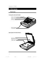
Page 10: ...nt view Closing the document feeder Document feeder indicators Document table Exit table Power switch Scanner indicators White sheet Document set origin Contact glass Opening the document feeder 03_IS...

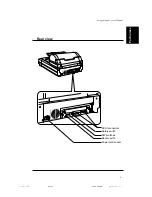
Page 11: ...3 Image Scanner User s Manual Rear view SCSI connectors Rotary switch DIP switches Reset switch Power cord socket Part names 03_IS430 BODY 97 5 8 5 35 PM Page 3 PageMaker 5 0J...

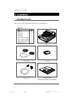
Page 12: ...Q ty Scanner 1 Power cord 1 Terminator 1 SCSI cable 1 User s manual English 1 User s manual German 1 User s manual French 1 Registration card 1 Terminator Power cord Scanner SCSI cable User s manuals...

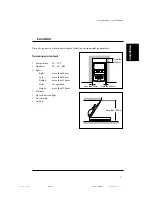
Page 13: ...emperature 10 32 C E Humidity 20 80 RH E Space Right more than 20 mm Left more than 20 mm Behind more than 130 mm Front for operation Height more than 720 mm E Flat base E Out of direct sunlight E No...

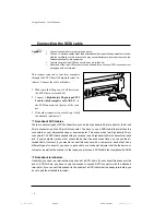
Page 14: ...connected device has such connectors you can use the at tached cable However if you want to connect this scanner with a computer or device that has a different type of connector you have to get a cab...

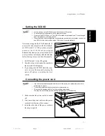
Page 15: ...ard follow the steps below to set the ID manually 1 Set DIP switch 3 to the ON positon 2 Turn the rotary switch and set the number to the desired SCSI ID number 3 If you change the SCSI ID while the s...

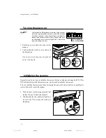
Page 16: ...sh the power switch again Power On Power Off Turning the power on Initializing the scanner ON Original position 1 2 3 4 5 6 7 8 OFF with SCAM ON without SCAM Generally you do not have to initialize th...

Page 17: ...is on the document feeder Lamp cover open Lamp error Document feeder cover open Paper jam Paper misfeed Document table error System error 3 Indicators Setting the document Meaning On Blinking Off The...

Page 18: ...document feeder document feeder mode Placing originals on the contact glass is the only way to scan books magazines and the like You can also scan single sheets this way Using the document feeder is...

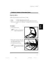
Page 19: ...l toner ink ball point pen anything that does not stick to the contact glass Document set origin 2 Put the original face down on the contact glass Place the upper left edge of the origi nal at the doc...

Page 20: ...Height is less than 12 mm Ex 20lb paper 100 24lb paper 85 E Paper Bond paper PPC paper or art coating paper E Thickness 0 07 0 16 mm E Written material Toner pencil marker ink water sign pen ball poi...

Page 21: ...ocu ment table until the green indicator of the document feeder lights Procedures 1 When scanning large size originals extend the document table Note If the extention of the document table is pushed d...

Page 22: ...isfeeds or soil the originals The above mentioned parts must always be kept clean Before scanning clean the contact glass the white sheet and the platen by wiping them with adry soft cloth Contact gla...

Page 23: ...ument feeder cover and clean the feed roller by wiping it with a damp cloth Caution Clean the roller after scanning an original written with material that doesn t stick well to the sheet such as penci...

Page 24: ...t solved by the measures given below contact your service representative for assistance Lamp cover open This indicates that the lamp cover is not closed 6 Troubleshooting Scanner Document feeder Green...

Page 25: ...the CCD does not sense light from the lamp The lamp may be burned out or the connector may be disconnected Corrective action Remove the lamp connector and then rein stall it correctly refering to pag...

Page 26: ...you can t see the document see steps 4 to 6 2 Pull out the jammed paper 3 Place the original again refering to Original condition and Procedure on page 12 and 13 4 Open the document feeder If you can...

Page 27: ...ition and Procedure on page 12 and 13 Document table error This indicates that the document table is not in the correct posititon Scanner Document feeder Green Amber Green Amber On Off Blinking Blinki...

Page 28: ...ter power is on Originals are not fed normally Scanned image is abnormal Corrective action Plug the power cord in Turn on the power Connect it securely Reset the computer Correct the SCSI ID Correct t...

Page 29: ...portrait by 200 dpi binary with the document feeder Scanning speed depends on the system environment Interface SCSI 2 Video interface with the optional video interface unit Power AC 120V 60Hz 220 240...

Page 30: ...se refer to your software manual for details The following functions are described Prescan Scan Scanning composition Binary scanning Threshold Halftone scanning Multi value scanning Area extraction Se...

Page 31: ...ed instead of DPI The higher the resolution the finer the detail Scan Function Scanning a selected area with all desired settings Usage Enter settings such as the scan area scanning composition resolu...

Page 32: ...16 64 or 256 levels Usage Use binary scanning to scan images with no gray shading such as text or line art Use halftone scanning to scan an image with gray shading such as a photograph to be printed o...

Page 33: ...ary composition when scanning binary images such as text and line draw ings black and white images without any gray areas You can select one of following two methods to set the threshold value in bina...

Page 34: ...terns of black and white dots Usage Use halftone scanning when scaning an image with gray shadings such as a photo graph to be printed or displayed on a monochrome device such as a laser printer Halft...

Page 35: ...bit data represents 256 different shades of gray Note that the multi value scanning uses more memory and disk space For example 8 bit scanning needs 8 times space more than binary 1 bit scanning of th...

Page 36: ...from a page define a rectangle over the photograph as shown below The position of the area is decided by setting the X and Y co ordinates of the left upper corner of the rectangle The size is decided...

Page 37: ...ct mode Reset the areas after decreasing the number of areas or their sizes Usage When scanning an original which includes binary images and halftone images you can scan each image with its own compos...

Page 38: ...ne mode Note This function is available only when the optional image processing unit is installed in the scanner If binary areas and halftone areas are not separated clearly segmentation may not be ac...

Page 39: ...ng time than a low resolution im age Note If the resolution is set at more than 400 dpi the maximum scanning width is less than 304 mm Usage Generally setting the scanning resolution at the resolution...

Page 40: ...e setting and shades of gray appear Conversely if a lighter image becomes pure white decrease the setting Contrast Function To adjust the contrast value between 1 and 255 At a high contrast setting th...

Page 41: ...Smooth Weakens contrast to soften an image Linear Outputs an image as scanned User defined Your own gamma correction curve is loaded into the scanner Usage Select one of them depending on your origina...

Page 42: ...s at following cases Noise elimination Use this filter when scaninng a document which is copied several times Black dots in a white area and white dots in a black area will be eliminated Edge extracti...

Page 43: ...angle the document is skewed and to send the skew angle to the host computer Semi automatic document feed SADF mode In this mode originals which are set on the feeder one at a time are automatically...

Page 44: ...up while sliding it to the left Caution Do not touch the middle of the lamp unit Hold the green parts only 8 To attach the red lamp unit go backwards through the previous steps You can use the option...

Page 45: ...ocessing unit The optional image processing unit adds the following image processing functions Dynamic threshold The scanned image is automatically binalized by an appropriate threshold The scanner di...

Reviews: