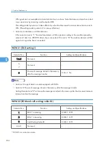
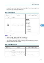


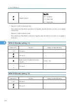


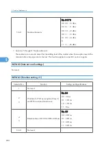


WSW40 (V.34 modem settings)
Selector No.
Function
Setting and Specifications
1
2
Not used.
-
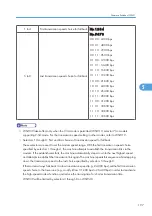
3 to 8
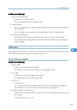
Masking of symbol rate(s)
0: Not masking
1: Masking
No. 3 = 0/1 3429 symbols/sec
No. 4 = 0/1 3200 symbols/sec
No. 5 = 0/1 3000 symbols/sec
No. 6 = 0/1 2800 symbols/sec
No. 7 = Not used.
No. 8 = 0/1 2400 symbols/sec
• WSW40 takes effect only when the V.34 mode is permitted (WSW19, selector 7) in models
supporting V.34 mode.
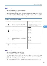
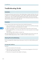
• Selectors 3 through 8: Masking of symbol rate(s)
These selectors allow you to limit the transmission speed range in V.34 mode by masking the desired
symbol rate(s). Transmission speeds assigned to the symbol rates are listed on the next page. The
setting made by these selectors will limit the setting made by selectors 1 through 4 on WSW39.
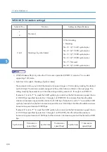
If selector 3 is set to "1" to mask the 3429 symbols/second when the first transmission speed choice
is 33600 bps (specified by selectors 1 through 4 of WSW39), for example, then the allowable
maximum transmission speed will be limited to 31200 bps. If selector 8 is set to "1" to mask the 2400
symbols/second when the first transmission speed choice is 33600 bps, then the allowable maximum
transmission speed remains 33600 bps.
If selector 8 is set to "1" to mask the 2400 symbols/second when the first transmission speed choice
is 21600 bps (specified by selectors 1 through 4 on WSW39), then the allowable maximum
transmission speed remains 21600 bps but the minimum transmission speed will be limited to 4800
bps.
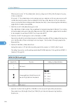
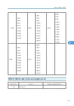
Symbol rate
Transmission
speed (bps)
Symbol rate
Transmission
speed (bps)
Symbol rate
Transmission
speed (bps)
5. Service Maintenance
198
5
Summary of Contents for HL-F1
Page 1: ...Model HL F1 Machine Code H558 Field Service Manual 14 May 2010...
Page 2: ......
Page 13: ...1 Product Information Specifications See Appendices for the Specifications 11 1...
Page 15: ...Rear View 12 USB Interface Connector 13 Back Cover 14 AC Power Connector Overview 13 1...
Page 18: ...Components The equipment consists of the following major components 1 Product Information 16 1...
Page 22: ...2 Installation 20 2...
Page 23: ...3 Preventive Maintenance PM Tables There are no PM parts for this machine 21 3...
Page 24: ...3 Preventive Maintenance 22 3...
Page 33: ...Disassembly Flowchart Before You Do 31 4...
Page 44: ...5 Remove the actuator R A from the panel unit B 4 Replacement and Adjustment 42 4...
Page 45: ...6 Release the four hooks to remove the panel rear cover A x 3 B M3x8 Common Parts 43 4...
Page 48: ...11 Remove the rubber key A 4 Replacement and Adjustment 46 4...
Page 60: ...22 Remove the CIS A 23 Disconnect the CIS harness A 4 Replacement and Adjustment 58 4...
Page 61: ...24 Remove the two CIS springs A 25 Remove the LF roller gear A Common Parts 59 4...
Page 63: ...28 Remove the scanning motor F sub ASSY A x 1 M3x6 Common Parts 61 4...
Page 107: ...2 Remove the main frame R A x 3 B M4x12 Main Body 105 4...
Page 110: ...FG harness ASSY 1 Main PCB 2 FG harness ASSY 3 Laser unit 4 Replacement and Adjustment 108 4...
Page 111: ...Regist sensor PCB ASSY 1 PS PCB unit 2 Regist sensor PCB ASSY 3 Chute Harness Routing 109 4...
Page 112: ...Fan Motor 60 Unit 1 Fan motor 60 unit 2 Main PCB 4 Replacement and Adjustment 110 4...
Page 120: ...CIS 1 Main PCB 2 CIS 4 Replacement and Adjustment 118 4...
Page 155: ...10 Click Next Firmware Installation 153 5...
Page 156: ...11 To proceed click Yes 5 Service Maintenance 154 5...
Page 218: ...Image Defects 6 Troubleshooting 216 6...
Page 255: ...Model HL F1 Machine Code H558 Appendices 14 May 2010...
Page 256: ......
Page 258: ...2...


