


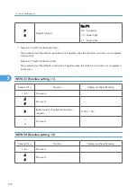


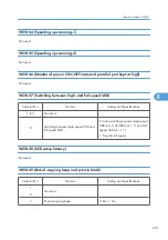


• Selector 1: Printout of the stored image data of an unsent document onto an error report
This selector determines whether or not to print out the 1st-page image data of a document onto the
error report if the document image data stored in the temporary memory cannot be transmitted
normally.
• Selector 2: Erasure of the stored image data of an unsent document at the time of the subsequent in-
memory message transmission
If in-memory message transmission fails repeatedly when selector 1 is set to "1," the temporary memory
will be occupied with image data. Setting selector 2 to "1" will automatically erase the stored 1st-
page image data of an unsent document at the time of the subsequent in-memory message transmission
only when recording paper or toner runs out.
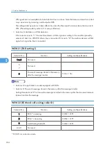
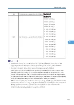
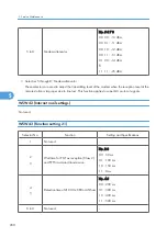
WSW38 (V.34 transmission settings)
Selector No.
Function
Setting and Specifications
1
2
Setting of the equalizer
No. 1 2
0 X : Automatic
1 0 : Fixed to 4 points
1 1 : Fixed to 16 points
3
Sending level of guard tone at phase 2
0: Normal - 7 db 1: Normal
4
Stepping down the transmission speed at
fallback each
0: 2400 bps 1: 4800 bps
5
6
Automatic control of modem's EQM gain
for proper transmission
speed choice
No. 5 6
0 0 : For higher transmission speed than
the current setting
0 1 : No change from the current setting
1 0 : For lower transmission speed than
the current setting
1 1 : For further lower transmission than
the setting made by 1, 0
7
Redialing when a communications error
occurs
0: ON 1: OFF
8
Detection of CED for stopping CNG
0: ON 1: OFF
Firmware Switches (WSW)
195
5
Summary of Contents for HL-F1
Page 1: ...Model HL F1 Machine Code H558 Field Service Manual 14 May 2010...
Page 2: ......
Page 13: ...1 Product Information Specifications See Appendices for the Specifications 11 1...
Page 15: ...Rear View 12 USB Interface Connector 13 Back Cover 14 AC Power Connector Overview 13 1...
Page 18: ...Components The equipment consists of the following major components 1 Product Information 16 1...
Page 22: ...2 Installation 20 2...
Page 23: ...3 Preventive Maintenance PM Tables There are no PM parts for this machine 21 3...
Page 24: ...3 Preventive Maintenance 22 3...
Page 33: ...Disassembly Flowchart Before You Do 31 4...
Page 44: ...5 Remove the actuator R A from the panel unit B 4 Replacement and Adjustment 42 4...
Page 45: ...6 Release the four hooks to remove the panel rear cover A x 3 B M3x8 Common Parts 43 4...
Page 48: ...11 Remove the rubber key A 4 Replacement and Adjustment 46 4...
Page 60: ...22 Remove the CIS A 23 Disconnect the CIS harness A 4 Replacement and Adjustment 58 4...
Page 61: ...24 Remove the two CIS springs A 25 Remove the LF roller gear A Common Parts 59 4...
Page 63: ...28 Remove the scanning motor F sub ASSY A x 1 M3x6 Common Parts 61 4...
Page 107: ...2 Remove the main frame R A x 3 B M4x12 Main Body 105 4...
Page 110: ...FG harness ASSY 1 Main PCB 2 FG harness ASSY 3 Laser unit 4 Replacement and Adjustment 108 4...
Page 111: ...Regist sensor PCB ASSY 1 PS PCB unit 2 Regist sensor PCB ASSY 3 Chute Harness Routing 109 4...
Page 112: ...Fan Motor 60 Unit 1 Fan motor 60 unit 2 Main PCB 4 Replacement and Adjustment 110 4...
Page 120: ...CIS 1 Main PCB 2 CIS 4 Replacement and Adjustment 118 4...
Page 155: ...10 Click Next Firmware Installation 153 5...
Page 156: ...11 To proceed click Yes 5 Service Maintenance 154 5...
Page 218: ...Image Defects 6 Troubleshooting 216 6...
Page 255: ...Model HL F1 Machine Code H558 Appendices 14 May 2010...
Page 256: ......
Page 258: ...2...


