background image

Setting Up

32

Test Printing

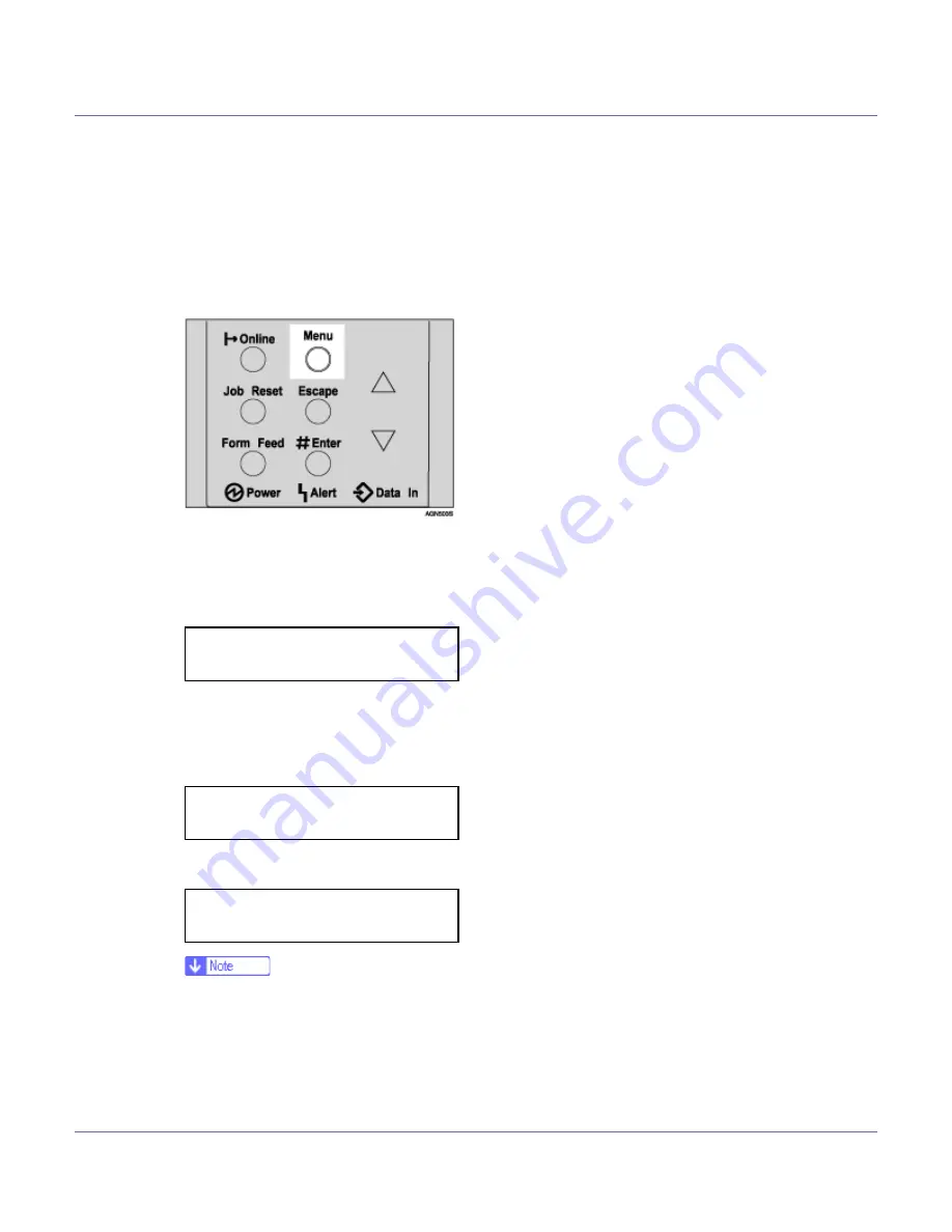
The following explains the procedure for test printing of the configuration page.

Test print in order to verify that the printer is working normally. Test printing
checks printer performance only; it does not test the connection to the computer.

A

Press the 

{

Menu

}

 key.

The 

[

Menu

]

 screen appears on the display.

B

Press the 

{U}

 or 

{T}

 key to display [

List/Test Print

], and then press the 

{

#

Enter

}

 key.

The menu for selecting the contents to be test printed appears.

C

Press the 

{U}

 or 

{T}

 key to display [

Config. Page

], and then press the 

{

#

Enter

}

 key.

The following message appears and the configuration page is printed.

If printing is not normal, check to see if an error message appears on the
display. If there is an error message, see “Troubleshooting”, Maintenance
Guide.

D

Check the options.

  Menu:

   List/Test Print

  List/Test Print

   Config. Page

  Printing...


Summary of Contents for Aficio AP610i

Page 1: ...ENERGY STAR Program 9 Manuals for This Printer 10 How to Read This Manual 11 Guide to the Printer Exterior 12 Inside 14 Control Panel 15 Setting Up Where to Put the Printer 17 Unpacking the Printer and Checking the Contents of the Box 20 Installing the Toner Cartridge 22 Loading Paper 26 Turning the Power On 29 Selecting the Display Language 30 Test Printing 32 ...

Page 2: ...e F 54 Attaching Bluetooth Interface Unit Type C 61 Attaching Hard Disk Drive Type 2600 68 Attaching Network Data Protection Unit Type B 70 Attaching Duplex Unit AD610 72 Connecting the Printer Network Connection 75 USB Connection 77 Parallel Connection 78 IEEE 1394 Connection 79 Configuration Ethernet Configuration 80 IEEE 802 11b Wireless LAN Configuration 85 IEEE 1394 Configuration 91 IP over 1...

Page 3: ...ndows operating systems are as follows Microsoft Windows 95 operating system Microsoft Windows 98 operating system Microsoft Windows Millennium Edition Windows Me The product names of Windows 2000 are as follows Microsoft Windows 2000 Advanced Server Microsoft Windows 2000 Server Microsoft Windows 2000 Professional The product names of Windows XP are as follows Microsoft Windows XP Professional Mi...

Page 4: ...In this manual the following important symbols are used Indicates a potentially hazardous situation which if instructions are not followed could result in death or serious injury Indicates a potentially hazardous situation which if instructions are not followed may result in minor or moderate injury or damage to property ...

Page 5: ...cause burns or a fire Plug and unplug the power cord with dry hands or an electric shock could occur Do not risk electric shock by handling the power cord or plug with wet hands Do not remove any covers or screws other than those specified in this manual Some parts of the machine are at a high voltage and could give you an electric shock Also if the machine has laser systems di rect or indirect re...

Page 6: ...Consult a doctor if necessary If your skin comes into contact with toner or used toner wash the affected area thoroughly with soap and water If toner or used toner gets into your eyes flush immediately with large amounts of water Consult a doctor if necessary If toner or used toner is swallowed dilute by drinking a large amount of wa ter Consult a doctor if necessary Avoid getting toner on your cl...

Page 7: ...t Doing so may cause a malfunction or a burn The inside of this printer becomes very hot Do not touch parts labelled v indicating a hot surface Touching these parts will result in burns Grip the plug not the cord when pulling the plug from the socket Pulling the cord causes wear and tear that can result in fire or electric shock Lifting the paper feed unit carelessly or dropping it may cause injur...

Page 8: ...se flashback when exposed to open flames The inside of this printer becomes very hot Do not touch parts with this label in dicating a hot surface Touching these parts will result in burns The inside of this printer becomes very hot Do not touch parts with this label in dicating a hot surface Touching these parts will result in burns The inside of this printer becomes very hot Do not touch parts wi...

Page 9: ...les representa tive for recommended paper As an ENERGY STAR Partner we have deter mined that this machine model meets the EN ERGY STAR Guidelines for energy efficiency The ENERGY STAR Guidelines intend to establish an international energy saving system for developing and introducing energy efficient office equipment to deal with environmental issues such as global warming When a product meets the ...

Page 10: ...mation about paper replacing supplies and dealing with paper jams and error messages Software Guide HTML Provides basic information about installing the printer driver and software us ing the printer in a network environment and configuration and setup Also provides information about configuring and monitoring printer status us ing software and a Web browser Some functions cannot be used depending...

Page 11: ... this sym bol Be sure to read the instructions all of which are described in the Safety In formation section The statements above are notes for your safety If this instruction is not followed paper might be misfed originals might be dam aged or data might be lost Be sure to read this This symbol indicates information or preparations required prior to operating This symbol indicates precautions for...

Page 12: ...inting on custom paper size printer driver set tings are required Up to 100 sheets of plain paper 80 g m2 20 lb can be loaded See Paper and Other Media Supported by this Printer and Loading Paper in the By pass Tray Maintenance Guide 4 Output Tray Extension Pull out this extension when printing on long paper 5 Control Panel Contains keys for the printer operation and a panel display that shows the...

Page 13: ... sheet at a time Clean the friction pad when more than one sheet of paper is fed into the printer Also replace the friction pad when the message Replace Maintenance Kit appears 13 Paper Tray Cover Attach it when pulling out the tray extension of the paper tray 14 Power Cord Connect this cord into a wall outlet 15 Rear Cover Remove to install the optional duplex unit or to replace the fusing unit 1...

Page 14: ...aper 4 Registration Roller Feeds the paper If it becomes dirty clean it See Cleaning the Registration Roller Maintenance Guide 5 Transfer Roller Cover Open this cover when replacing a transfer roller 6 Transfer Roller When Replace Maintenance Kit appears on the panel display replace this roller 7 Fusing Unit Lock Levers Lift these levers when replacing the fusing unit 8 Fusing Unit Fuses the image...

Page 15: ...s on the display See Error Status Messages on the Control Panel Maintenance Guide 4 Data In indicator Blinks while the printer is receiving data from a computer Is on if there is data to be printed 5 Online key Press this key to switch the printer between online and offline 6 Job Reset key When the printer is online press this key to cancel any ongoing print job See Canceling a Print job Software ...

Page 16: ... the display 10 Enter key Press this key to execute menu items selected on the display Press this key to clear some errors See Troubleshooting Maintenance Guide 11 U T keys Use these keys to increase or decrease values on the display when making settings Keep the key pressed to quicken scrolling and increase or decrease values on the dis play in units of 10 ...

Page 17: ...l Avoid multi wiring Do not damage break or make any modifications to the power cord Do not place heavy objects on it pull it hard or bend it more than nec essary These actions could cause an electric shock or fire Do not handle the plug with wet hands Doing so might cause an electrical shock Keep the machine in an area that is within optimum environmental condi tions Operating the machine in an e...

Page 18: ... level within 5 mm 0 2 from both front to rear and left to right To avoid possible build up of ozone locate this machine in a large well ven tilated room that has an air turnover of more than 30 m3 hr person When you use this machine for a long time in a confined space without good ventilation you may detect an odd smell To keep the workplace comfortable we recommend you keep it well ventilated En...

Page 19: ...y cold hot or humid Locations near air conditioners or humidifiers Locations near other electronic equipment Locations subject to frequent strong vibration Power Source Connect the power cable to a power source of the following specification 120 V 60 Hz 8 4 A or more ...

Page 20: ...you use is appropriate for your computer Manuals and CD ROMs Setup Guide This manual Maintenance Guide CD ROM Printer Drivers and Utilities CD ROM Display Version Manuals HTML CD ROM Print Version Manuals PDF Parts Paper Tray Cover Additional Documentation B Remove the plastic bag Lift the printer and move it to the place where you want to install it When lifting the machine use the inset grips on...

Page 21: ...Setting Up 21 Lower the machine slowly and carefully to prevent trapping your hands ...

Page 22: ...or used toner is inhaled gargle with plenty of water and move into a fresh air environment Consult a doctor if necessary If your skin comes into contact with toner or used toner wash the affected area thoroughly with soap and water If toner or used toner gets into your eyes flush immediately with large amounts of water Consult a doctor if necessary If toner or used toner is swallowed dilute by dri...

Page 23: ... depending on the paper type size contents and settings Toner cartridges consumable are not covered by warranty However if there is problem contact the store where they ware purchased A Open the front cover by pushing the front cover release button B Remove the fixing material inserted between toner cartridge and the printer C Lift the front side of the toner cartridge and then pull it out of the ...

Page 24: ...remove the tape completely before installing the toner cartridge Otherwise the printer might be damaged If you pull out the strips when the toner cartridge is slant or standing on its side the cartridge might cause trouble with the printer Be sure to pull the tape horizontally Pulling it upward or downward may cause the toner to scatter After pulling the tape out of the cartridge toner scatters ea...

Page 25: ...ressing the indentations on the left and right sides Do not close the front cover with force If you cannot close the cover easily pull out the toner cartridge from the printer and insert it again After that close the front cover again Dispose of removed fixing material and tape in the same manner as ordi nary plastic waste ...

Page 26: ...e the tray Misfeeds might occur Do not mix different types of paper in a single paper tray A Lift the paper tray slightly and then pull it out until it stops Do not touch the three white pins on the left front of the printer B Lift the front side of the tray and then pull it out of the printer Do not pull out the paper tray forcefully If you do the tray might fall and cause an injury ...

Page 27: ...ide the tray Confirm that the paper fits under the rear guides When loading paper other than A4L long edged feed or 81 2 11L long edged feed adjust the paper size dial to match the size and feed direction of the paper in the paper tray When loading paper other than A4K short edged feed or 81 2 11K short edged feed you should extend the tray ...

Page 28: ...matches the sizes and feed direction of the paper in the tray Otherwise the printer might be damaged or a printing problem might occur Do not slide the paper tray in and out with force If you do the front and side paper guides will move out of the place For details about usable types of paper see Loading Paper Maintenance Guide ...

Page 29: ...b Off B Plug in the power cable Make sure the power cable is plugged securely into the wall outlet Turn the power off when plugging and unplugging the power plug C Turn the power to a On The power indicator on the control panel lights up Plug and unplug the power cable with dry hands or an electric shock could occur ...

Page 30: ...nt to use the display in English the following procedures are unnecessary The default setting is English A Press the Menu key The Menu screen appears on the display B Press the U or T key to display Language C Press the Enter key The following message appears on the display D Press the U or T key until the language you want to select appears Menu Language Language English ...

Page 31: ...Setting Up 31 E Press the Enter key Wait for two seconds The Menu screen appears on the display F Press the Online key The initial screen appears Ready ...

Page 32: ...e display B Press the U or T key to display List Test Print and then press the Enter key The menu for selecting the contents to be test printed appears C Press the U or T key to display Config Page and then press the Enter key The following message appears and the configuration page is printed If printing is not normal check to see if an error message appears on the display If there is an error me...

Page 33: ...Setting Up 33 For details about the configuration page see Interpreting the Configura tion Page Software Guide E Press the Online key The initial screen appears Ready ...

Page 34: ... feeder C Install the SDRAM module Memory Unit Type C 256MB Install the module to the SDRAM module slot on the controller board D Install the 1394 interface unit 802 11b interface unit or Bluetooth inter face unit Install the 1394 interface unit 802 11b interface unit or Bluetooth interface unit on the controller board The 1394 interface unit IEEE 802 11b interface unit or Bluetooth interface unit...

Page 35: ...ex unit to the rear of the printer Installing Options Install options in the positions shown in the illustration Exterior 1 Paper Feed Unit Type 610 Tray 2 or Tray 3 You can load up to 500 sheets 60 105 g m2 16 28 lb of plain paper into the tray See p 38 Attaching Paper Feed Unit Type 610 A maximum two paper feed units Type 610 can be attached Top most optional paper feed unit is displayed Tray 2 ...

Page 36: ...Duplex Unit AD610 Interior 1 802 11b Interface Unit Type F See p 54 Attaching 802 11b Interface Unit Type F 2 1394 Interface Unit Type 4510 See p 48 Attaching 1394 Interface Unit Type 4510 3 Bluetooth Interface Unit Type C See p 61 Attaching Bluetooth Interface Unit Type C 4 Memory Unit Type C 256MB SDRAM module See p 43 Attaching Memory Unit Type C 256MB SDRAM Module 5 Network Data Protection Uni...

Page 37: ...Installing Options 37 For the specifications of each option see Maintenance Guide ...

Page 38: ...paper feed units cannot be attached Check the printer nameplate to confirm the model code A Check the package contains the following Paper Feed Unit including a paper tray B Turn off the power of the printer and then unplug the printer s power ca ble and the interface cable C Remove the adhesive tape from the paper feed unit The printer weighs about 20 kg 44 1 lb When lifting the machine use the i...

Page 39: ...able back into the wall outlet and then turn on the power After finishing installation you can check whether the paper feed unit is properly installed Print the configuration page from the List Test Print menu If it is installed properly you will see Paper Feed Unit Tray 2 or Paper Feed Unit Tray 2 Paper Feed Unit Tray 3 under the Options list If the paper feed unit is not installed properly repea...

Page 40: ...Installing Options 40 See Loading Paper Maintenance Guide When adjusting the printing position see Adjusting Tray Registration Maintenance Guide ...

Page 41: ...her the main unit s feed tray Tray 1 nor Tray 3 can be used for this purpose Do not slide more than one paper tray out at the same time Having more than one full paper tray fully extended could cause the machine to topple The following explanation uses the example of installing the envelope feeder unit in Tray 2 A Check the package contains the following Envelope Feeder B Pull out the second paper...

Page 42: ... 2 The tray of the top most optional paper feed unit is beneath the paper tray Keep the paper tray with paper in a cool dark place C Lift the front of the envelope feeder and slide it carefully into the printer until it stops For information about loading paper see Loading Envelopes Mainte nance Guide ...

Page 43: ... the memory unit Before using the new memory unit you must make settings in the printer driv er A Turn off the power of the printer and then unplug the printer s power ca ble and the interface cable B If the duplex unit is attached push down the lever on right side and pull out the duplex unit until it stops If the duplex unit is not attached go to the following steps C Remove the two screws holdi...

Page 44: ... 44 The removed screws are required in fastening the controller board D Pull out the handle of the controller board E Pull the handle and then slide the controller board out F Place the controller board on a flat surface ...

Page 45: ...lot shown in the illustration below H Remove the default memory unit before installing a new memory unit Press down the levers on both sides to remove the default memory unit I Align the notch of the memory unit to the slot and then push it down un til it clicks ...

Page 46: ...ntroller board to the top and bottom rail using the T mark and then slide it into the printer slowly until it stops K Push the handle of the controller board until it clicks L Fasten the controller board to the printer with the two screws ...

Page 47: ...memory unit is properly installed Print the configuration page from the List Test Print menu If it is installed properly you will see the memory capacity for Total Memory To expand memory remove the default SDRAM module and then install the SDRAM module 256 MB Total Memory will be the size of SDRAM module memory unit you installed If the memory unit is not properly installed repeat the procedure f...

Page 48: ...ack 1 or later The client cannot install the printer driver without using an ac count that has administrators access rights Before touching the 1394 interface unit ground yourself by touching some thing metal to discharge any static electricity Static electricity can damage the 1394 interface unit Do not plug or unplug the 1394 interface cable while installing the printer driv er Use the 1394 inte...

Page 49: ...g the printer s power ca ble and the interface cable C If the duplex unit is attached push down the lever on right side and pull out the duplex Unit until it stops If the duplex unit is not attached go to the following steps D Remove the two screws holding the controller board in place Use a coin or similar object if the screws do not turn easily ...

Page 50: ...dle of the controller board F Pull the handle and then slide the controller board out G Place the controller board on a flat surface H Remove the two screws and the cover of the 1394 interface unit mount ing bracket These screws are used again in fastening the 1394 interface unit to the controller board ...

Page 51: ...1 The removed cover is not used when installing the 1394 interface unit I Attach the 1394 interface unit to the controller board Insert the end of the 1394 interface unit into the opening and then push down until it clicks ...

Page 52: ...1394 interface unit to the controller board K Match the controller board to the top and bottom rail using the T mark and then slide it into the printer slowly until it stops L Push back the handle of the controller board until it clicks ...

Page 53: ...unit is properly installed Print the configuration page from the List Test Print menu If it is installed properly you will see IEEE1394 for Controller Option You need to make settings with the control panel before using the 1394 in terface unit For more information see p 91 IEEE 1394 Configuration If the 1394 interface unit is not installed properly repeat the procedure from the start If you canno...

Page 54: ...ny static electricity Static electricity can damage the 802 11b inter face unit Do not subject the 802 11b interface unit to physical shocks A Check the package contains the following 802 11b Interface Unit Type F Interface Unit Card Do not touch the inside of the controller board compartment Doing so may cause a machine malfunction or a burn ...

Page 55: ...duplex unit is attached push down the lever on right side and pull out the duplex unit until it stops If the duplex unit is not attached go to the following steps D Remove the two screws holding the controller board in place Use a coin or similar object if the screws do not turn easily These screws are used again in fastening the controller board ...

Page 56: ...oller board out G Place the controller board on a flat surface H Remove the two screws and the cover of the 802 11b interface unit mounting bracket These screws are used again in fastening the 802 11b interface unit to the controller board The removed cover is not used when installing the 802 11b interface unit ...

Page 57: ...ns 57 I Attach the 802 11b interface unit Insert the end of the 802 11b interface unit into the opening and then push down until it clicks J Fasten the 802 11b Interface Unit to the controller board with the two screws ...

Page 58: ... the label facing down and the uneven black antenna surface facing up until it stops L Match the controller board to the top and bottom rail using the T mark and then slide it into the printer slowly until it stops M Push back the handle of the controller board until it clicks ...

Page 59: ...e power cable to the left side groove of the duplex unit and then slide the duplex unit in until it is connected to the printer If the duplex unit is not attached this step is not necessary After finishing installation you can check the 802 11b interface unit is prop erly installed Print the configuration page from the List Test Print menu If it is installed properly you will see IEEE 802 11b for ...

Page 60: ...ou cannot install it properly even after reinstallation con tact your sales or service representative You need to make settings with the control panel before using the 802 11b interface unit For more information see p 85 IEEE 802 11b Wireless LAN Configuration For printing the configuration page see p 32 Test Printing ...

Page 61: ...e Bluetooth interface unit touch something metal to discharge static electricity Static electricity can damage the Bluetooth inter face unit Do not subject the Bluetooth interface unit to physical shocks A Check the package contains the following Bluetooth Interface Unit Type C Interface Unit Card Do not touch inside the controller board compartment Doing so may cause a machine malfunction or a bu...

Page 62: ...lex unit is attached push down the lever on right side and then pull out the duplex unit until it stops If the duplex unit is not attached go to the following steps D Remove the two screws holding the controller board in place Use a coin or similar object if the screws do not turn easily These screws are used again in fastening the controller board ...

Page 63: ...er board out G Place the controller board on a flat surface H Remove the two screws and the cover of the Bluetooth interface unit mounting bracket These screws are used again in fastening the Bluetooth interface unit to the controller board The removed cover is not used when installing the Bluetooth interface unit ...

Page 64: ...s 64 I Attach the Bluetooth interface unit Insert the end of the Bluetooth interface unit to the opening and then push down until it clicks J Fasten the network interface unit to the controller board with the two screws ...

Page 65: ...g up slowly insert the card into the interface unit until it stops L Match the controller board to the top and bottom rail using the T mark and then slide it into the printer slowly until it stops M Push back the handle of the controller board until it clicks ...

Page 66: ... 66 N Fasten the controller board to the printer with the two screws O Press the antenna to extend it P Attach the antenna cap to the card with the side that has both corners of the antenna cap cut out facing the screws ...

Page 67: ...u can check the Bluetooth interface unit is properly installed Print the configuration page from the List Test Print menu If it is installed properly you will see Bluetooth for Controller Op tion If the Bluetooth interface unit is not installed properly repeat the procedure from the start If you cannot install it properly even after reinstallation con tact your sales or service representative For ...

Page 68: ...n damage the hard disk drive A Check the package contains the following Hard Disk Drive Type 2600 B Turn off the power of the printer and then unplug the power cable C Remove the two screws and the cover of the hard disk drive mounting bracket Use a coin or similar object if the screws do not turn easily The screws and cover are not used when installing the hard disk drive ...

Page 69: ...ck whether the hard disk drive is properly installed Print the configuration page from the List Test Print menu If it is installed properly you will see Printer Hard Disk Drive for Controller Option If the hard disk drive is not installed properly repeat the procedure from the start If you cannot install it properly even after reinstallation contact your sales or service representative For printin...

Page 70: ...ata protection unit from physical shocks Use the under slot for the data protection unit A Check the package contains the following Network Data Protection Unit Type B B Turn off the power of the printer and then unplug the power cable C Remove the card slot cover at the back of the printer ...

Page 71: ...ction unit until the card clicks into the place E Reattach the cover over the network data protection unit Fasten the screw to secure the cover Do not touch the network data protection unit while the machine is in use It may come loose even if pushed only slightly ...

Page 72: ...aper feed unit the paper feed unit must be attached prior to attaching the duplex unit Check the printer nameplate to confirm the model code A Check the package contains the following Duplex Unit B Turn off the power of the printer and then unplug the power cable C Remove the adhesive tapes ...

Page 73: ... cover by pushing the two knobs as shown in the illustra tion E Remove the rear cover in the horizontal direction The rear cover of the printer is not used when attaching the duplex unit Store the removed rear cover for possible future use ...

Page 74: ... listed in the column of configuration options then it has been properly installed If the duplex unit is not installed properly repeat the procedure from the start If you cannot install it properly even after reinstallation contact your sales or service representative If the printing position is not correct adjust the registration of the trays For more information about adjusting the registration ...

Page 75: ... to the machine s Ethernet port Use shielded Ethernet cable Unshielded cables create electromagnetic inter ference that could cause malfunctions Ethernet cable is not supplied with this machine Select your cable according to the network environment A Connect the Ethernet cable to the Ethernet port B Connect the other end of the cable to the printer s network such as a hub For details about network...

Page 76: ...Connecting the Printer 76 1 Green lit when the printer is properly connected to the network 2 Yellow lit when 100BASE TX is being used Unlit when 10BASE T is be ing used ...

Page 77: ...r 2003 Mac OS 9 x and Mac OS X v10 3 or higher Windows 98SE Me supports USB1 1 speeds USB connection with Macintosh is only possible via the printer s USB port A Connect the square shaped connector of the USB2 0 cable to the USB port B Connect the opposite end s flat connector to devices such as your com puter s USB interface or a USB hub For details about settings for USB connection printing see ...

Page 78: ...parallel cable and host computer par allel port Use shielded interface cable Unshielded cables create electromagnetic inter ference that could cause malfunctions A Turn off the printer and computer B Connect the cable to the interface connector C Securely attach the other end of the parallel cable to your computer s parallel port Secure the cable For details about settings for parallel connection ...

Page 79: ... meters 14 8 feet long A Connect the interface cable to the 1394 interface unit B Connect the other end to the host computer You can use either connector Either of the two connectors for the 1394 interface unit can be used If you have an interface cable with a ferrite core connect the ferrite core end to the printer For details about settings for parallel connection printing see Software Guide ...

Page 80: ...l The following table shows the control panel settings and their default values These items appear in the Host Interface menu If DHCP is in use IP Address Subnet Mask and Gateway Address are all set automatically Make this setting only when it is necessary See Software Guide A Press the Menu key Setting Name Value DHCP On IP Address 011 022 033 044 Subnet Mask 000 000 000 000 Gateway Address 000 0...

Page 81: ...Not Active selection screen appears F Press the U or T key to select Active or Not Active and then press the Enter key After the settings are made about two seconds later the screen returns to the active protocol menu G Set other protocols you need to set in the same way H Press the Escape key the screen returns to the network setup menu The default is Active Leave unused protocols Not Active Enab...

Page 82: ...cape key when no value is entered and the screen will return to the network setup menu without the IP address changing K Make the other settings in the same way and then press the Enter key After the settings are made about two seconds later the screen returns to the network setup menu L If you use TCP IP assign Subnet Mask and Gateway Address following the same procedure for entering the IP addre...

Page 83: ...ng Auto When you first select Auto the frame type detected by the printer is adopted If your network can use more than two frame types the printer may fail to select the correct frame type if Auto is selected In this case select the appropriate frame type Q Press the U or T key to display Frame Type NW and then press the Enter key The current setting appears on the display R Press the U or T key t...

Page 84: ...onfiguration 84 S Press the Online key The initial screen appears T Print a configuration page to confirm the settings made For details about printing the configuration page see p 32 Test Printing Ready ...

Page 85: ...Gateway Address DHCP Frame Type NW and Active Protocol under the Network Setup menu For details about setting items under Configuring the Printer for the Network see Software Guide The 802 11b interface unit cannot be used simultaneously with a standard ethernet interface In the SSID menu if blank is specified in 802 11b Ad hoc mode or Ad hoc mode ASSID appears A Press the Menu key The Menu screen...

Page 86: ...etting menu The factory default is 802 11 Ad hoc To use an IEEE 802 11b card for which the SSID Network Name setting is not necessary select Ad hoc The transmission mode of IEEE 802 11b can also be set using a Web browser For details see Web Image Monitor Help and Using Web Image Monitor Software Guide F If 802 11 Ad hoc or Ad hoc is selected for Comm Mode set the channel to use for transmission C...

Page 87: ...are Guide K Press the U or T key to display SSID and then press the Enter key The following message appears on the display If an SSID has been set you can check the set SSID Press the Enter key L Press the U or T key to display Enter ID and then press the Enter key The following message appears on the display The value in brackets at the upper right is the number of characters entered M Press the ...

Page 88: ...ollowing message appears on the display R Press the U or T key to display Active and then press the Enter key The following message appears on the display When setting the WEP Setting to Active you will need to enter the WEP key If you have not entered the key be sure to enter it If you have entered the WEP key and change the setting press the U or T key to display No and then press the Enter key ...

Page 89: ...that can be entered is limited to 10 or 26 for hexadecimal and 5 or 13 for ASCII If you try to enter too many characters the following message appears hexadecimal ASCII For ASCII character strings each capital letter and lowercase letter is rec ognized respectively To display the previous character press the Escape key U After entering the key press the Enter key After the settings are made about ...

Page 90: ...Configuration 90 The initial screen appears W Print a configuration page to confirm the settings made For details about printing the configuration page see p 32 Test Printing Ready ...

Page 91: ...94 and Subnet Mask1394 are automatical ly set IP over 1394 A Press the Menu key The Menu screen appears on the display B Press the U or T key to display Host Interface and then press the Enter key The interface setting menu appears C Press the U or T key to display IEEE 1394 Setup and then press the Enter key Setting Name Value DHCP On IP Address1394 011 022 033 044 Subnet Mask1394 000 000 000 000...

Page 92: ...et Also do not specify the same subnet mask Do not set 011 022 033 044 as the IP address To get the IP address for the printer contact your network administrator G Press the U or T key to enter the left most entry field of the IP ad dress and then press the Enter key The pointer k moves to the next entry field automatically The value moves by 10 if the U or T key is kept pressed You can return the...

Page 93: ...on Page Software Guide SCSI print A Press the Menu key The Menu screen appears on the display B Press the U or T key to display Host Interface and then press the Enter key The interface setting menu appears C Press the U or T key to display IEEE 1394 Setup and then press the Enter key The IEEE 1394 setting menu appears D Set SCSI print and Bidi SCSI print if necessary The default setting is Active...

Page 94: ...ress the Enter key After the settings are made about two seconds later the screen returns to the IEEE 1394 setting menu G Set Bidi SCSI print in the same way H Press the Online key The initial screen appears I Print a configuration page to confirm the settings made For details about printing the configuration page see p 32 Test Printing SCSI print Active Ready ...

Page 95: ...must have an account that has Manage Printers permission Log on as an Administrator Only the printer driver and not the SmartDeviceMonitor for Client is installed when using this printer under USB parallel or 1394 connection If you con nect using USB see Software Guide A Quit all applications currently running B Insert the CD ROM into the CD ROM drive The installer starts Auto Run may not work wit...

Page 96: ...t dialog box of the installer and then take out the CD ROM To stop installation of the selected software click Cancel before installa tion is complete Restart the computer and then reinstall the other software or printer drivers Auto Run may not work with certain operating system settings If this hap pens launch Setup exe on the CD ROM root directory Select a printer to whose IP address is display...

Page 97: ...certain operating system setting If this is the case launch Setup exe on the CD ROM root directory C Select an interface language and then click OK D Click Install manuals E Follow the instructions on the screen to complete the installation F Click Finish when the installation is completed G Click Exit Auto Run may not work under certain operating system setting If this is the case copy all datas ...

Reviews: