Install Conduit, Cabling, and J-Boxes
17
8.1
Flexible Conduit Sections
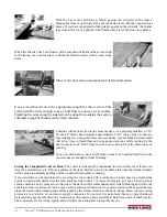
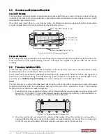
All areas of cabling where rigid conduit might affect load cell deflection must
use flexible cable sections. This includes cable sections adjacent to load cells as
in the photo at left. In this application, a threaded LB fitting connects the flexible
section to the rigid conduit running beneath the scale deck to the junction box on
the opposite siderail.
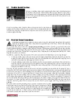
For axle-weighing scales, flexible cable sections must also be used between
separate scale sections to allow free movement of the two independent decks. A
circular loop of flexible conduit between separate scale sections provides extra
assurance against binding.
8.2
Electrical Ground Connections
Grounding requirements for outdoor electronic scales is a poorly-understood concept that often results in
improper grounding systems that corrupt data from ground-loop current flows, invite costly lightning
damage to load cells, or both.
As a general rule, always strive for a
single-point grounding
system. Do not drive ground rods at the scale
location which establishes a separate earth ground for the scale. This separate earth ground will not share the same
zero reference as the existing earth ground for the AC power system. This difference in electrical potential invites
ground-loop current flow between the two grounds, often corrupting data communication like RS-232 which
depends on a stable zero reference.
In addition, a separate earth ground system at the scale can actually invite lightning or power surge damage!
•
A minor powerline surge in the scale house electrical supply should immediately be shunted to ground. If a
separate ground system exists at the scale with a lower potential than the main ground, the surge may travel
out to the scale ground rod, damaging load cells on its way.
•
A nearby lightning ground strike may instantly raise the zero potential of a ground rod at the scale location,
while leaving the scale house ground rod unaffected less. That lightning surge will now take the easiest
path to the lower-potential ground—through the scale wiring and back to the scale house ground, possibly
damaging the indicator on its way.
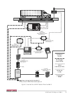
Therefore, the best grounding system for the scale is the same grounding system used for the incoming AC power
system.The 120 VAC power source used to power the indicator will be connected to an existing earth grounded rod
system at the scale house or other building where the indicator is located. This should consist of a double ground
rod system of two 5/8" x 8' copper rods driven 8' deep at the service entrance where the local utility company
brings their lines into the building. The local utility company can test the resistance of the existing ground rods
with a clamp-on megohmeter that measures zero resistance. A reading of 3¾ or less is acceptable as a ground. If
the test determines that the grounding system is inadequate, the utility company can suggest methods to improve
the system. It’s crucial that the scale owner authorize and make the recommended improvements to assure an
adequate electrical ground. Do not connect the scale to the AC power supply until the grounding system is
adequate.
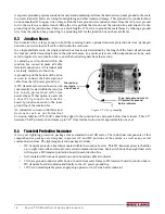
Be certain each load cell grounding strap is securely connected to the top plate
and bottom plate of each load cell mount. This strap is designed to channel
power surges on the deck around—rather than through—the load cell to ground.
These, and all, ground connections must be torqued tightly and retightened at
regular service intervals. A thick coating of anti-oxidant grease should be
maintained on all ground connections to prevent corrosion.
Summary of Contents for Survivor SR
Page 1: ...SURVIVOR SR Siderail Truck Scale Assembly Instructions 45698 Rev D...
Page 2: ......
Page 29: ......


