Installation
©
Rice Lake Weighing Systems
●
All Rights Reserved
7
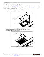
5. Insert one end of the 20 ft (6.1 m) cable into the junction box through free cord grip.
6. Connect the wires to the required terminals as indicated in
.
7. Pull out excess and tighten strain relief bushing to securely hold the cable.
Figure 2-6. Junction Box Terminal Blocks with Indicator Connectors Identified
8. While creating a strain relief loop at the scale (to facilitate future lifting of the scale for servicing or cleaning) route the
interface cable to the indicator.
9. When the interface cable is in position, wire the cable to the indicator. See the indicator manual for correct wiring
arrangement.
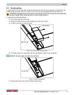
IMPORTANT: If the site has potential dangers, a method of protection is required, such as running the cable in conduit or in
a floor channel.
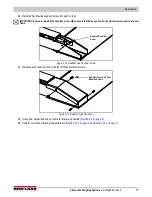
Figure 2-7. Interface Cable Protection
10. When the interface cable is protected and in its final position, check all strain relief fittings for tightness and if
necessary trim corners as described in
.
JP4
JP 2
PT4
PT3
JP3
PT1
EXP
PT2
JP1
1
CELL4
1
CELL1
1
CELL3
1
CELL2
IND
-EX
-SI
SHD
+SI
+EX
M
R
N
I
-SI
S2C
I
A
G
+EX
+SI
-SI
SHD
-EX
I
S
G
A
L
T
+SI
M
S
I
N
L
T
R
+EX
-EX
-SI
SHD
+SI
+EX
+SI
-EX
-SI
SHD
-EX
SHD
+SE
-SE
+EX
Indicator Connections
Cable Color Code
Junction Box
Red
+ Excitation
Black
- Excitation
Green
+ Signal
White
- Signal
Brown
Shield
Yellow
+ Sense
Blue
- Sense
Table 2-1. Junction Box Connections
Floor
Steel Cover
Load Cell Cable
Steel Cover
Load Cell Cable
Bolt

