


Installation and Wiring
13
2.7
Serial Communications
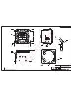
The serial communications cable from the IQ plus 310 XPCD has been connected to the intrinsic safety barriers
at the factory,(see Figure 2-4). The barriers are located in the bottom of the enclosure.
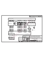
Wire the serial communications cable to terminal block TB6 (shown below).
Figure 2-6. Serial Communications Wiring
2.8
Configuration and Setup
The IQ plus 310 XPCD configuration is the same as the normal IQ plus 310A. Please refer to the
IQ plus 310A
Installation and Operation manual
, PN 22979 for further details on configuring your indicator.
Enable the configuration parameters by toggling the switch at the top of the indicator mounted inside the
enclosure. Configure the indicator at this time.
ZERO
GROSS/NET
TA
R
E
UNITS
COMMON
+SEN
-SIG
+SIG
-SEN
SHIELD
+EXC
-EXC
-SENSE
JUMPER
JUMPER
+SENSE
TB1
TB3
TB2
TB4
WIRE TERMINATION OF
EXTERIOR SWITCHES
L1
L2
GND
TB7
TB8
Revision REV
, NEW
ASSEMBY P/N 66036
TXD
GND
DIGIN 1
DIGIN 2
TB5
TB6
TXD
GND
DIGIN 1
DIGIN 2
TB5
TB6
-SENSE
JUMPER
JUMPER
+SENSE
DISCONTINUED


