


Installation
5
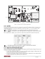
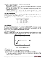
Figure 2-2. IQ plus 210 CPU and Power Supply Board
2.3.2
Load Cells
Wire the load cell cable from the load cell or junction box
to connector J5 as shown in Table 2-2. If using 6-wire
load cell cable (with sense wires), remove jumpers JP1 and JP2 (see Figure 2-2). For 4-wire installation, leave
jumpers JP1 and JP2 on.
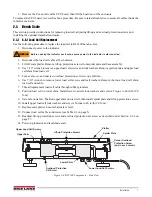
All models come with ten feet of color-coded load cell cable. Do not cut this cable. The load cell is
temperature-compensated for an exact cable length often feet. Cutting the load cell cable voids the load cell
warranty.
When connections are complete, use two cable ties to secure the load cell cable to the inside of the enclosure.
Use grounding procedure described in Section on page 4 to attach shield wire to backplate.
For 6-wire connections, remove jumpers JP1 and JP2.
2.3.3
Setting the Load Cell Compensation Jumper
The load cell compensation jumper (above the
ZERO
button location on the CPU board; see Figure 2-2) must be set
for the type of load cell connected to the indicator:
•
For load cells with balanced bridges, set the jumper in the OFF position. Example of balanced load cells
include the RL1040, RL1250, RL1260, RL1380, and RL1385.
•
For load cells with unbalanced bridges, follow the procedure below to determine the correct jumper position.
Examples of unbalanced cells include the RL1042 and RL1010.
J5 Pin
Function
RL1040
RL1042
RL1380
1
+SIG
Red
White
2
–SIG
White
Red
3
+SENSE
Blue
--
4
–SENSE
Brown
--
5
+EXC
Green
Green
6
–EXC
Black
Black
Table 2-2. J5 Pin Assignments and Load Cell Wire Color
F1
F2
Blue wire
J8
Brown wire
J1
To setup switch
J7
1
2
3
SERIAL COMM
TxD
GND
RxD
VR3
LOAD CELL CONNECTOR
1
2
3
4
5
6
7
–SIG
+SENSE
–SENSE
SHIELD
+EXC
–EXC
+SIG
J5
J2
J3
1
1
GND
DIGIN 2
DIGIN 1
J6
J4
GND
BR1
–
+
VR1
VR2
JP1
JP2
RESET
ANALOG
+5V
TEST
DIGITAL
+5V
TEST
TP1
TP2
A / D C o n v e r t e r
Microprocessor
Tr a n s f o r m e r
U N I T S
B u t t o n
Z E R O
B u t t o n
P o w e r
I n p u t
Note
Note
Summary of Contents for IQ plus 2100
Page 2: ...IQ plus 2100 Digital Bench Scale Version 1 Installation Manual PN 53415 Rev A...
Page 3: ......
Page 42: ......


