Page
34
/
60
4.3- Electrical requirements
With a 230V~ 50Hz motor, the log splitter should be connected to standard 230V
10% (50Hz
1Hz).
The electrical supply must be fitted with protection devices of under-voltage, over-voltage, and
over-current as well as a residual current device (RCD), which maximum residual current rated at
0.03A.
Electrical connection rubber cables must comply with EN60245 which are always marked with
H07RN, and with cross section greater than 1.5mm
2
.
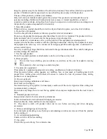
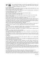
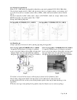
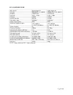
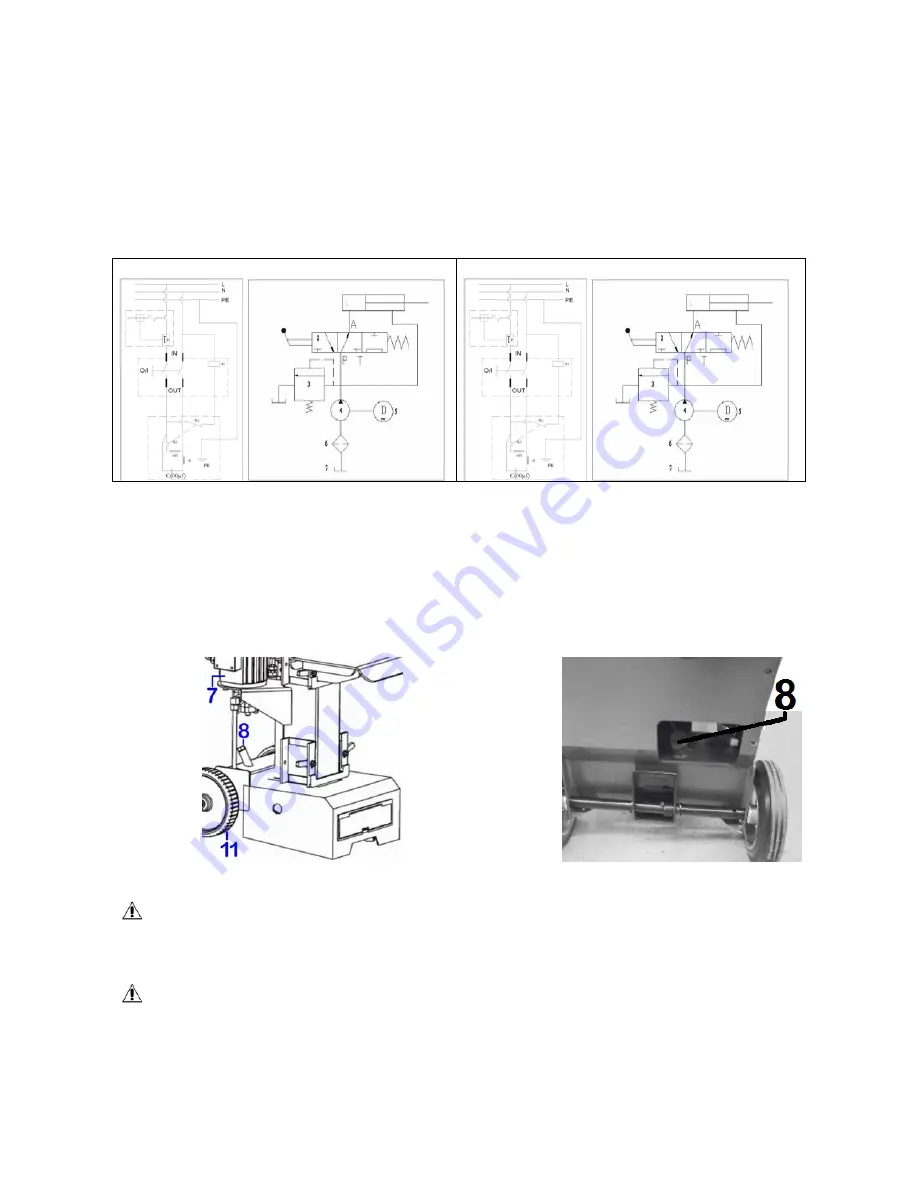
Wiring and Plumbing diagrams
For log splitter 8T PREHLS7T/V / 042091
For log splitter 7T PREHLS71T/VE / 042111
4.4- Bleed the air
Always open the air bleed valve before starting operating the log splitter
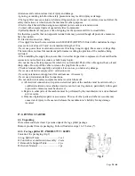
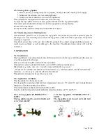
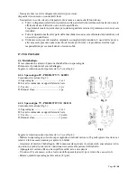
4.4.1- For log splitter 8T PREHLS7T/V / 042091
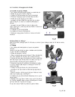
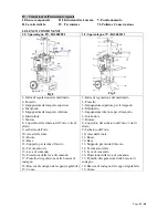
- Loosen the air bleed valve (8 in Fig.15) (oil tank
cover) a few turns whenever the splitter is being used.
- Keep air bleed valve (8) opened during operation.
- Retighten this air bleed valve (8) once you finished.
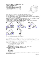
4.4.2- For log splitter 7T PREHLS71T/VE / 042111
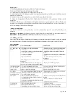
- Loosen the air bleed valve (8 in Fig.16) (oil tank
cover) a few turns whenever the splitter is being used.
- Keep air bleed valve (8) opened during operation.
- Retighten this air bleed valve (8) once you finished.
Fig.15
Fig.16
Failure to loosen the bleed screw will keep the sealed air in the hydraulic system.
The air being compressed and then decompressed, such continuous air compression and
decompression will blow out the seals of the hydraulic system and cause permanent damage to the
log splitter.
Before moving or transporting the log splitter, close the bleed screw to avoid any spillage.

