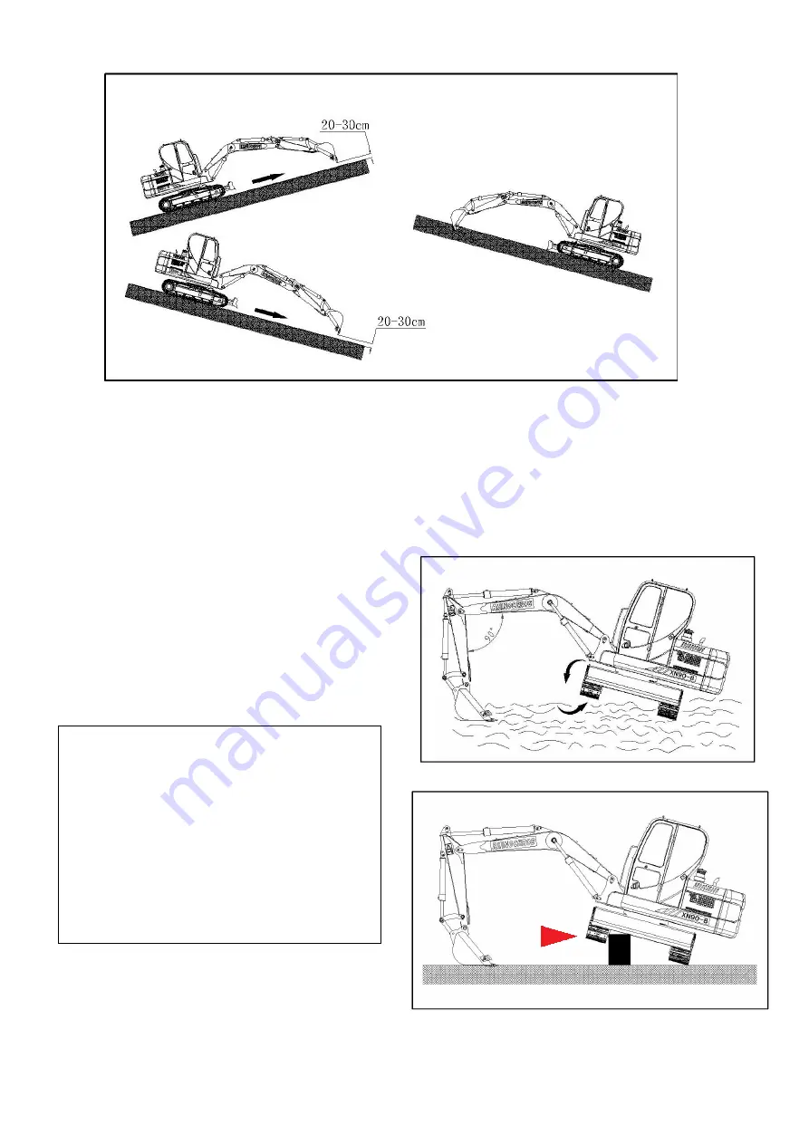
background image

Fig 3-31

8. Walking along the slope, do not walk across the slope.(Fig 3-31),pull out of the bucket
rod, lowering the boom,keep the bucket a 300mm distance from the ground, if the machine
sliding or unstable, put down the bucket to keep control.If the engine stopped, low down
the bucket,make sure all handle at the middle position before restart the engine.

9. If there is dust or sands on the trak shoe,
lift the two track shoes and turn to clear it.
Make sure the sludge is cleared.
( Fig3-32 Fig 3-33)

Fig 3-32

Fig 3-33

▲ WARNING

If to support any part of the excavator by

boom or arm, swing the bucket to make sure

the under part of the bucket touch ground, and

the angle between boom and arm should be

90 degree

48 

Summary of Contents for XN80-E

Page 1: ...em Pressure MPa 22 Hydraulic System Flow L min 150 Pilot Pump DOOSAN Valve Rexroth Swing Motor EATON Max Swing Speed r min 9 r min Travel Motor EATON Speed km h H 3 7km h L 2 3 km h Bucket Digging For...

Page 2: ...Max Digging Depth mm 3540 Max Digging Radius mm 6240 Standard Machine With A C A C Standard Packing Way 2 units in a 40HQ Passed Certificates CE ISO...

Page 3: ...not taken WARNING denotes a reminder of safety practices or directs attention to unsafe practices if proper precautions are not taken NOTICE describes operation and maintenance procedures which should...

Page 4: ...ests and ear protection Always tilt up the safety lever before leaving the operator s seat Do not carry tools replacement parts or other supplies while climbing on or off the excavator Never use the s...

Page 5: ...ng coolant At or near operating temperature the engine coolant is hot and under pressure and could cause severe burns Check the coolant level only after the radiator cap is cool enough to touch Remove...

Page 6: ...g the excavator is free of other personnel and that no one is working on or under the excavator before starting the engine After entering the cab adjust the operator s seat and controls the inside and...

Page 7: ...safe distance In case you do touch a high voltage line by accident proceed as follows Do not leave the machine Move the machine if possible from the danger zone until you obtain sufficient distance W...

Page 8: ...t be visible by the operator and or must be in voice contact with him Depending on the attachment combination it is possible for the bucket teeth to hit the cab the cab protection or the boom cylinder...

Page 9: ...ithin the permitted limits Check that there is enough clearance underneath all bridges underpasses utility lines and in tunnels During the unloading procedure proceed with the same care and caution as...

Page 10: ...r repairing parts or components make sure they are mounted very carefully on lifting devices to prevent any possible danger Use only suitable and technically sound lifting devices make sure that lifti...

Page 11: ...injuries and fires Even if hoses and lines are stored and used properly they undergo a natural aging process For that reason their service life is limited Improper storage mechanical damage and improp...

Page 12: ...pecially the wind may make the opening of the door uneasy Sit down on the seat fast your seat belt and start the machine It is essential to have your seat belt fastened if you want to operate the mach...

Page 13: ...50 working hours and use the designated fuel according to the Operation Maintenance Manual 3 Warning Sign To keep space from the stick 4 Identification Tags Indicates the Model Manufacturer Operating...

Page 14: ...tem 7 Adjustment of seat 8 Safe belt 9 Front glass 10 Control bar of door 11 Inside lights of the cab OPERATION AND CONTROL OPERATION AND CONTROL contains the following items WARNING Warning light buz...

Page 15: ...necting rod 7 connecting rod 8 bucket 9 swing platform 10 engine hook 11 fuel tank 12 hydraulic oil tank 13 cab 14 balance weight 15 dozer blade 16 dozer blade cylinder 17 guide pulley 18 idler strain...

Page 16: ...Left joystick 9 Travelling bar 13 Radio 2 Starting switch 6 Right joystick 10 trabelling bar 3 Horn switch 7 The engine throttle handle 11 The safety bar 4 A C systerm control panel 8 Dozer control ro...

Page 17: ...hts on B off position turn to this position the engine flameout electric system power off C switch on position turns to this position engine on Fig 2 4 1 Instrument panel WARNING Starting switch is wi...

Page 18: ...pressor stop b blowing rate switch Fig 2 6 left switch blowing rate switch is to control the blowing rate there are three grades O position fan stop position L low blowing rate position M middle blowi...

Page 19: ...10 Traveling joystick These two joysticks control the forward and back of the machine 11 Safety pole The safety pole is to lock the joystick when the machine travel Fig 2 12 The joystick control the...

Page 20: ...12 Radio Refer to the sound...

Page 21: ...e 106 it indicate the red area and the buzzer sound press the mute button the buzzer stop sound 2 Fuel level indicator the LCD blue area indicate when the fuel tank oil level is above 10 of the oil ta...

Page 22: ...it is sound press the button now the mute indicator light buzzer stop sound 5 Working head lights press the button the indicator lights light the head lights work now if the indicator light out the h...

Page 23: ...r When there is some sand or dirt on the glass please clean the glass first then use the windshield unless it may break the glass or the wiper 10 walking speed press the high speed button the high spe...

Page 24: ...se block Keyset Fig 2 15 1 Alarm relay when the electric switch is on the alarm relay is connected and output control signal When the alarm relay makes sound the electric system has faults now the mac...

Page 25: ...s to control the starting motor on the engine when the starting switch is on ON position starting compound relay supply power to motor to start the motor At the same time it collects all the signals f...

Page 26: ...wind Fig 2 17 rotate the air outlet direction accordingly to get proper outlet direction Fig 2 16 turn the wind speed switch anticlockwise to O position the AC turn off now Refrigeration elementary op...

Page 27: ...e body once Water Leakage will cause water shortage make the engine overheating In winter to protect the Radiator core body be not cracking is important too In order to prevent the cooling liquid icin...

Page 28: ...Sound system Fig 2 18 1 Controller and switch ON OFF volume pause play random digital LCD function switch sound mode former next FM AM USB 1...

Page 29: ...lect the radio frequescy you want 3 The radio station design method 1 Press the power switch to turn on the radio Frequency will show on the digital screen 2 Choose your wanted channel by adjust the t...

Page 30: ...ck adjustment Seat adjustment Fig 2 19 Move the adjusting rod to adjust the proper position left right adjustment range 160mm Seat adjustment Lift the adjusting rod on the left of the seat to get the...

Page 31: ...Fig 2 20 Fig 2 20 3 Lifting the window and lock on the top of the cab by using these two handles Fig 2 21 4 Screw up the two locking pins to make sure its safe Fig 2 24 NOTE reverse the procedures to...

Page 32: ...Push the action bar as the indicated direction to open the lock Fig 2 23 Interior lamp in the cab Press the switch the lamps works Fig 2 24 Action bar of open and close door...

Page 33: ...he 80 of the rated speed when the machine is grinding in 1 5 The following inspections should be carried after the 8 hours grinding in 1 5 1 Check if there is some noise or over heated of each transmi...

Page 34: ...ires and the connectors 2 Fuel system drain the water and impurity from the fuel tank 3 Hydraulic system check the leakage of hydraulic oil tank and tubes 4 Lubrication carefully conduct daily and reg...

Page 35: ...gine cooling liquid temperature gauge charging warning light fuel gauge engine oil pressure warning light Fig 3 3 Engine starting 1 Check according to the procedures of engine before starting 2 Put th...

Page 36: ...the key Fig 3 6 6 Heating up according to the hydraulic systerm Ref Fig 3 7 7 Check all the operation instructions after heating up make sure the engine systerm oil presure and cooling liquid work un...

Page 37: ...lerator handle on the level of a little higher than the idle speed 3 Sound horn 4 Put the switch at Open plase fig 3 8 wait 15 seconds start atonce Fig 3 8 Instrument panel indicator light Indicator d...

Page 38: ...icating lamp make sure the engine systerm fuel presure cooling liquid working in normal condition 8 To heating up according to the state of low temperature hydraulic system Using Auxiliary boost batte...

Page 39: ...e negative side of auxiliary battery to the earth point of the upper platform do not Fig 3 11 connect to the negative pole of the battery directly 3 start the engine as instructed 4 After the engine i...

Page 40: ...rking devices then turn Fig 3 14 clockwise for 3 cycles then anticlockwise for 3 times 5 Put the working device on ground to let one side of the track shoe off ground on a firm ground the other side t...

Page 41: ...The hydraulic oil in the hydraulic system For 5 minutes NOTE do not let the cylinder to reach Two dead points 5 Put the acceleration bar on the high speed position Fig 3 19 6 Reat the procedures of 3...

Page 42: ...y Stop the engine NOTE running the engine idly for 3 5 minutes before shop the engine unless the heat may cause problem to the engine 1 Park the excavator on level and firm ground Fig 3 21 2 Put the w...

Page 43: ...engine stop 1 If the excavator oil or coolant liquid leak check and repair 2 Check the working devices and under part 3 Refilling fuel 4 Clear the combustibles around the engine such as leaf paper and...

Page 44: ......

Page 45: ......

Page 46: ...X N 9 0 8 X N 9 0 8 X N 9 0 8...

Page 47: ...ne stopped low down the bucket make sure all handle at the middle position before restart the engine 9 If there is dust or sands on the trak shoe lift the two track shoes and turn to clear it Make sur...

Page 48: ...1 If only control one operating rod forward or backward the excavator will circle around the still track shoe Fig 3 35 Fig 3 35 WARNING There needs a trailer to transport the machine is the displaceme...

Page 49: ...ally and park Fig 3 37 Action bar ISO NOTES When you start to work move the handles slowly to check the rotary motion and front working assembly The structure of action bar on this excavator meet to t...

Page 50: ...realize rotary brake Fig 3 40 Note The following phenomenon are normal it is not the excavator s problem The bucket arm may desitate when working when the bucket arm is working the oil supply may not...

Page 51: ...X N 9 0 8 X N 9 0 8 X N 9 0 8 X N 9 0 8 X N 9 0 8 X N 9 0 8 X N 9 0 8 X N 9 0 8 X N 9 0 8...

Page 52: ...X N 9 0 8 X N 9 0 8 X N 9 0 8 X N 9 0 8 X N 9 0 8 X N 9 0 8 X N 9 0 8 X N 9 0 8 X N 9 0 8 X N 9 0 8 X N 9 0 8 X N 9 0 8...

Page 53: ...X N 9 0 8 X N 9 0 8 X N 9 0 8 X N 9 0 8 X N 9 0 8 X N 9 0 8...

Page 54: ...X N 9 0 8 X N 9 0 8 X N 9 0 8...

Page 55: ...X N 9 0 8 X N 9 0 8 X N 9 0 8 X N 9 0 8 X N 9 0 8 X N 9 0 8...

Page 56: ...X N 9 0 8 X N 9 0 8 X N 9 0 8 X N 9 0 8 X N 9 0 8 X N 9 0 8...

Page 57: ...X N 9 0 8 X N 9 0 8 X N 9 0 8 X N 9 0 8 X N 9 0 8 X N 9 0 8...

Page 58: ...X N 9 0 8 X N 9 0 8 X N 9 0 8 X N 9 0 8 X N 9 0 8 X N 9 0 8...

Page 59: ......

Page 60: ...ne off When working in the engine area make sure the covers and side doors are secured Only add fuel when the engine is turned off Never smoke or allow an open flame in refueling area Cleanliness is v...

Page 61: ...washer fluid denatured alcohol 5 0 L Fuel Use only fuel with a sulfur content of less than 0 5 and not less than the requirement of GB252 94 115L Diesel Engine 16 4L Anti freeze The max anti freeze t...

Page 62: ...ne lubrication oil fuel and coolant please see the Operation Maintenance Manual for Engine CHECKING THE COOLANT LEVEL When the cool ant is cold the coolant level should be no lower the Low line To che...

Page 63: ...the coolant also has to be drained from the cooling pump TO ADD THE COOLANT AND VENT THE COOLING CIRCUIT Reinstall the cover of the drain valve close the plug and add the coolant to the expansion tan...

Page 64: ...ine is used under hard conditions or in multi shift service lubricate more often up to once a day LUBRICATION OF ATTACHMENT BEARING POINTS The main lubrication points are as follow Cylinders and boom...

Page 65: ...placed every time when the hydraulic oil is changed every 500 working hours CHECK THE HYDRAULIC OIL LEVEL When checking the oil level park the machine on the level ground put down the boom stick and r...

Page 66: ...dd the oil via the opening of the breather valve 2 until the oil level reaches the middle level on the sight gauge Close the breather valve 2 Add some more oil to the tank remove the return cover 1 un...

Page 67: ...ire extinguisher and sensors Notice when washing the excavator with high pressure water or hot water A Keep a 0 5m distance between the cleaner and the washed parts B Water temperature must be limited...

Page 68: ...the monitor light is always on once a cleaned core is mounted replace it Take down a seal ring each time clearing dust In this way clearing times can be known from the seal rings If the CUSHION 4 or N...

Page 69: ...t for the lubricant may spurt out because of the high pressure The tensity is standard in below drawing Check the track bolts Check the track bolts once a week If loose screw it tight Force moment of...

Page 70: ...ponents directly When in the maintenance repair of the hydraulic system first release the pressure of the oil First go out the engine and then keep the starting key in the state of on trip the two ope...

Page 71: ...aulic pump Loose the drainage pipe 1 and make the air exhaust Once hydraulic oil pour from pipe should set the exhausting pipe in time When the first time starting or after maintenance aslo pure hydra...

Page 72: ...is running or fire disaster maybe caused wear the protective gloves and glasses when dealing with the battery no fire and spark around the electrolyte solution of the battery do not touch the solution...

Page 73: ...is less than 0 5mm no need to screw bolt2 tight 3 screw bolt2 and 3 tight After the adjustment gap b is bigger and a disappears In the illustration 5 is bucket 7 is stick Replace the wearing parts Bes...

Page 74: ...core 1st within 50 hours Replace oil 1st within 50 hours Replace fuel filter core 1st within 250 hours Clear water radiator blades Replace water filter core check the density of the anti corrosion add...

Page 75: ...fixing of the motor and reducer Working hours Swing circle Lubricating the bearing of the circle Lubricating the gear of the circle Check the fixing bolts Check the space of the gears Working hours T...

Page 76: ...exchanger Check the leakage of the air conditioner Working hours Frame undercarriage and working device Check the bucket teeth Inject lubricant Check the connection of all parts Check the balance wei...

Page 77: ...l Check whether there is air leaking into fuel system Check high pressure pump and oil spray mouth Check the air inlet space Check the compressed pressure of the engine Exhausted air is white or blue...

Page 78: ...on but the engine signal is not on Check the monitor Check the switch of the monitor Start switch is on but the light of battery is not on Check the monitor Check and repair the relevant wires The ke...

Reviews: