RHEINTACHO rotas CR Operating Instructions Manual Download Page 1


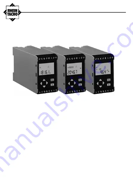
Programmable Speed Monitor 


rotas 

CR  

  CRR  

  CRA  

  CRRA


Operating Instructions 


B

A

: N

0000.

225C

/06

.202

RHEINTACHO Messtechnik GmbH 

Waltershofener Straße 1 

Tel. +49 (0)761 45 13 - 0 

Fax +49 (0)761 44 52 74 

79111 Freiburg 

Germany 

[email protected] 

www.rheintacho.com 


Summary of Contents for rotas CR

Page 1: ...r rotas CR CRR CRA CRRA Operating Instructions BA N0000 225C 06 2022 RHEINTACHO Messtechnik GmbH Waltershofener Stra e 1 Tel 49 0 761 45 13 0 Fax 49 0 761 44 52 74 79111 Freiburg Germany sales rheinta...

Page 2: ...C 2002 All rights reserved The contents of this booklet including data statements and drawings for the application and operation of the device are protected by copyright and may not be reproduced in a...

Page 3: ...before using the device and if any part is not understood contact the supplier for clarification before proceeding further Take care of the manual Always have it available during the service life of t...

Page 4: ...device and its functions 44 2 1 Technical features 44 2 2 Monitoring modes 46 2 3 Principle of measurement 48 3 Identification 50 3 1 Package contents 50 3 2 Labelling 50 4 Assembly and electrical con...

Page 5: ...power plants and ships The programmable device processes pulse signals received from revolution sensors moment of momentum or incremental measuring systems digital revolution measuring instruments an...

Page 6: ...immediately to the foreman electrician and to the plant manager The device should be isolated electrically and made safe from accidental operation If subsequent repairs involve dismantling the unit it...

Page 7: ...advise they appear adjacent to the certain parts of the text to emphasize the relative importance of that item DANGER Potential for injury or death ATTENTION Potential for damage to the device or appl...

Page 8: ...gure 1 In 1 Power supply UB Depending on the model the device will require 18 to 36 V DC or with a built in DC DC converter 10 to 36 V DC Signal input Figure 1 In 3 The device disposes of a variable s...

Page 9: ...nd optional Relay 2 Figure 1 Out 1 2 The output relays can be programmed for the following functions Change over function with selectable direction of contact i e normally open normally closed Speed m...

Page 10: ...the monitoring mode the LCD display shows Item 2 The current measured value Item 3 Optional Relay 2 Item 4 Relay 1 Item 5 Set value of relay 1 only displayed when set limits have been violated Item 6...

Page 11: ...ng and controlling Under speed monitoring After the starting bridge time has elapsed the active relay switches to the alarm mode if speed falls below the lower set limit the voltage drops below the st...

Page 12: ...easuring a number of frequency periods to give an average figure This is necessary to prevent fluctuations in switching response The actual number of periods used for averaging will depend on programm...

Page 13: ...ment time Measurement time n x time of a measurement period If the average measured value exceeds the trigger point within the measuring time the device reacts at the end of the current measurement ti...

Page 14: ...g Instruction booklet 3 2 Labeling There are two labels on the exterior of the device that show the following data Model Code Part Number Customers ID number If given The programmable parameters of th...

Page 15: ...DC 5820 100 CRRA 2 Relays with 18 36 V DC 5820 200 CR 1 Relay without 10 36 V DC DC 5813 100 CRR 2 Relays without 10 36 V DC DC 5813 200 CRA 1 Relay with 10 36 V DC DC 5823 100 CRRA 2 Relays with 10 3...

Page 16: ...ed is governed by the number of periods required to determine an average value For correct functioning this must be set up as described on page 65 4 1 Assembling The device is designed for attachment...

Page 17: ...owed Relay 1 with mains voltage 230 V and relay 2 with low voltage 24 V Allowed Relay 1 and relay 2 with mains voltage 230 V Allowed Relay 1 and relay 2 with low voltage 42 V INFORMATION The device do...

Page 18: ...GND 3 Sensor supply 12 V 4 Starting bridge 5 Starting bridge 6 FREE CRxA Analogue output 7 Power supply UB DC 8 Power supply UB DC 9 Relay 1 no 10 Relay 1 com 11 Relay 1 nc 12 FREE CRRx Relay 2 no 13...

Page 19: ...programming factory set Settings are shown on one of the two data labels attached to the housing After checking that these settings are correct the monitoring operation can be started Test Mode and Pr...

Page 20: ...is programmed Figure 7 Test Mode keys Activating the Test mode With the device running in the Monitoring Mode press and hold down the OK key and the UP arrow key the DOWN arrow key simultaneously Duri...

Page 21: ...f periods for the average 15 21 Trigger level signal input 6 0 V Behavior of the relays Relay 1 Relay 2 Optional 10 Limiting value 1000 0 3 0 11 Monitoring direction 12 Direction of contacts for the s...

Page 22: ...ultaneously Programme step 17 Thus special programming includes steps 1 to 3 steps 6 to 15 and steps 17 to22 During programming progress is indicated by a flashing cursor at the current entry If input...

Page 23: ...d these settings should be noted and retained on file for future reference Programming Abort Confirm Selection Setting numerals Figure 8 The programming keyboard INFORMATION Refer to the fold out diag...

Page 24: ...eps 3 or 4 at which time the display changes to therefore the new code must be noted If the device has been factory pre programmed the code is 11111 but the display reads For an existing code enter th...

Page 25: ...ensor to the internal circuitry of the device Setting options are pnp 10 k ohm Pull Down resistance at 0 V npn 10 k ohm Pull Up resistance at 12 V sin no resistance connected INFORMATION The trigger l...

Page 26: ...per unit see step 7 The software will not recognize an incorrect input Equation 1 ZE Z Q Hz M 20000 M Maximum value Q No of pulses unit of length ZE Unit of time Z Unit of time in sec Example no of pu...

Page 27: ...on for relay 1 This defines the relay contact position during the alarm state see Figure 9 Figure 9 Relay contact position in the alarm state Set the switch back value of relay 1 The switch back value...

Page 28: ...NFORMATION The function Switch back delay time is not available for Relay 2 Set the offset of the optional analogue output The offset has a default of 0 mA and must be set at this or at the alternativ...

Page 29: ...onds Set the number of periods required to average the measured value within the indicated minimum and maximum values see section 2 3 ATTENTION Potential for damage to the monitored system The switch...

Page 30: ...gh as possible to provide high disturbance resistance Proposal of the device Signal type Trigger on high low NPN PNP 6 0 V 2 5 V Sinus 2 5 V 1 0 V 0 7 V 0 2 V The device always indicates the higher tr...

Page 31: ...supply UB Voltage 18 36 V DC with DC DC converter 10 36 V DC optional Current consumption 160 mA at 24 V DC with DC DC converter 120 mA at 24 V DC Signal input Type NPN PNP or Sinus signal Internal re...

Page 32: ...e Change over contacts Switching voltage Safety note sect 4 2 AC 250 V DC 42 V Nominal switching current AC 5 A DC 2 A Nominal switching power 1250 VA Analogue output optional Type 0 20 mA or 4 20 mA...

Page 33: ...68 2 6 0 7 g 1 100 Hz Protective class Protective insulation EMV Norms Disturbance resistance EN 61326 1 EN 61326 A1 EN 61000 4 2 EN 61000 4 3 EN 61000 4 8 EN 61000 4 4 EN 61000 4 5 Disturbance sent...

Page 34: ...ting rail EN 50 022 Casing dimensions 43 70 114 mm W H D Casing material GFK polycarbonate inflammability class UL94 V 0 Terminals 16 screw clamps with tension contacts Connection cross section 1 2 5...

Page 35: ......

Page 36: ......

Page 37: ......

Reviews: