Rheem P16 Series Installation Instructions Manual Download Page 22

22

Tubing

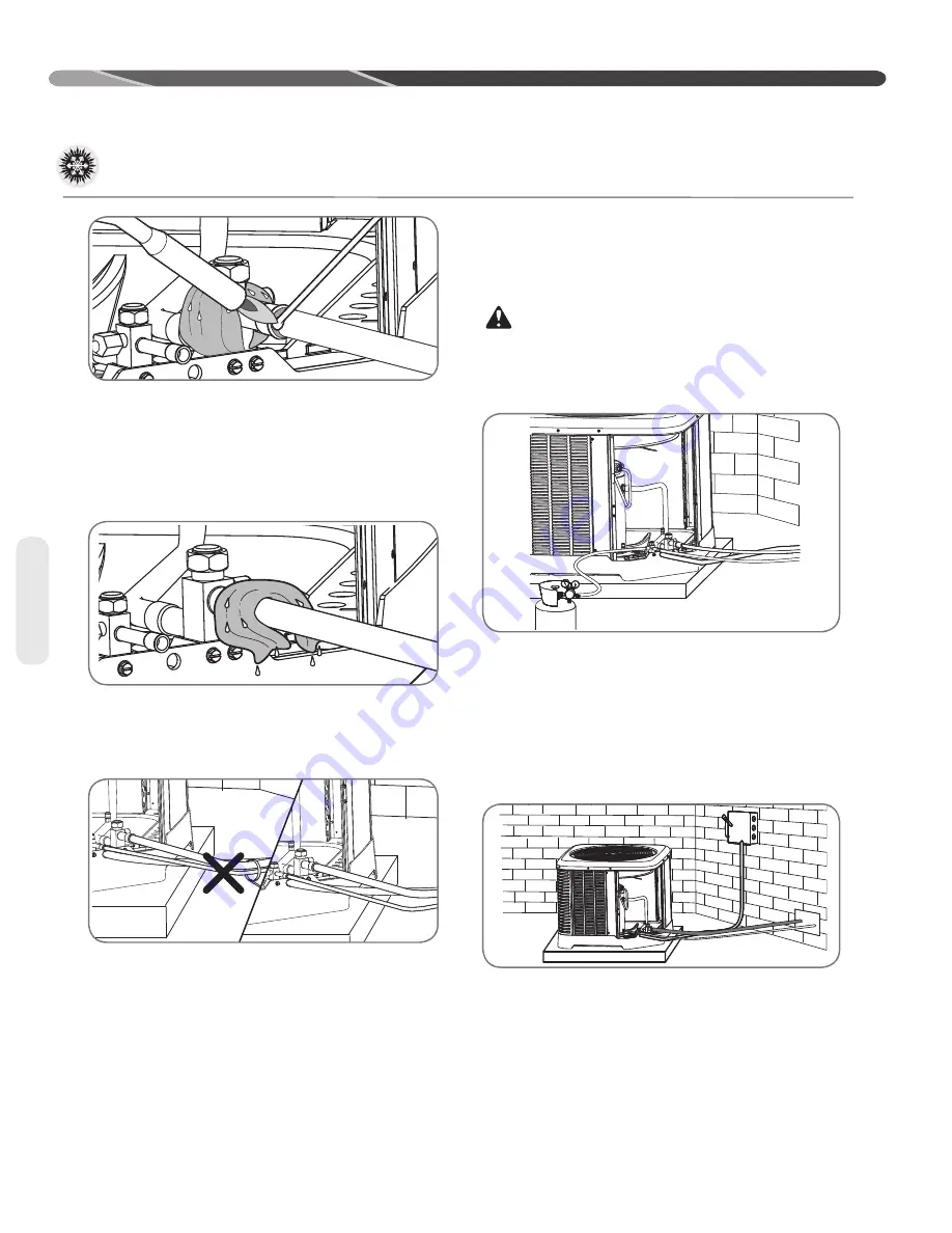
•  Braze the tubing between the outdoor unit and 

indoor coil. Flow dry nitrogen into a pressure port 

and through the tubing while brazing, but do not 

allow pressure inside tubing which can result in 

leaks. Once the system is full of nitrogen, the 

nitrogen regulator should be turned off to avoid 

pressuring the system.

•  After brazing, use an appropriate heatsink material 

to cool the joint.

•  Reinstall the Schrader cores into both pressure 

ports.

•  Do not allow the vapor line and liquid line to 

be in contact with each other. This causes an 

undesirable heat transfer resulting in capacity 

loss and increased power consumption.

Leak Testing

Indoor coils have only a holding charge of dry 

nitrogen. Keep all tube ends sealed until 

connections are to be made.

WARNING:


Do not use oxygen 

to purge lines or pressurize system for leak test. 

Oxygen reacts violently with oil, which can cause 

an explosion resulting in severe personal injury or 

death.

•  Pressurize line set and coil through service fittings 

with dry nitrogen to 150 PSIG maximum. Close 

nitrogen tank valve, let system sit for at least 

15 minutes, and check to see if the pressure has 

dropped. If the pressure has dropped, check for 

leaks at the line set braze joints with soap bubbles 

and repair leak as necessary. Repeat pressure 

test. If line set and coil hold pressure, proceed 

with line set and coil evacuation (see page 21).

•  The vapor line must be insulated for its entire 

length to prevent dripping (sweating) and prevent 

performance losses. Closed-cell foam insulation 

such as Armaflex and Rubatex

®

 are satisfactory 

insulations for this purpose. Use 1/2" [12.7 mm] 

minimum insulation thickness. Additional 

insulation may be required for long runs.

INSTALLATION

Interconnecting Tubing (cont.)

ST-A1226-07-00

ST-A1226-06-00

Summary of Contents for P16 Series

Page 1: ...PROPER INSTALLATION ADJUSTMENT AND OPERATION OF THIS UNIT READ THESE INSTRUCTIONS THOROUGHLY BEFORE ATTEMPTING INSTALLATION OR OPERATION FAILURE TO FOLLOW THESE INSTRUCTIONS MAY RESULT IN IMPROPER INS...

Page 2: ...ol Wiring 23 Typical Thermostat Wiring Diagrams 23 Power Wiring 24 Grounding 24 Start Up 25 29 Start Up 25 Checking Airflow 25 Evacuation Procedure 26 Final Leak Testing 26 Checking Refrigerant Charge...

Page 3: ...e R 22 service equipment or components on R 410A equipment Use appropriate care when using this refrigerant Failure to exercise care may result in equipment damage or personal injury Only match this o...

Page 4: ...any Check model number electrical characteristics and accessories to determine if they are correct Check system components indoor coil outdoor unit air handler furnace etc to make sure they are proper...

Page 5: ...92 250 1723 COPELAND 55 23156 47 9195 None SP1624AJ2NA RP1636AJ2NA 156 4423 208 230 1 60 17 0 17 0 83 2 8 1 3 25 25 40 40 30 30 550 3792 250 1723 COPELAND 55 23156 36 9196 None SP1636AJ2NA RP1648AJ2NA...

Page 6: ...SS ALLOW 24 610 mm OF CLEARANCE AIR INLET LOUVERS ALLOW 6 152 mm OF CLEARANCE ALL SIDES 12 305 mm RECOMMENDED P 16 24 A J 2 N A MINOR SERIES Z TYPE 2 TWO STAGE VOLTAGE J 1 PH 208 230 60 A NATIONAL HEA...

Page 7: ...onents However proper refrigerant charge and proper airflow are critical to achieve rated capacity and efficiency Installation of this product should follow the manufacturer s refrigerant charging and...

Page 8: ...operation Closely follow the clearance recommendations on page 8 24 61 0 cm to the service panel access 60 152 4 cm above heat pump fan discharge unit top to prevent recirculation 6 15 2 cm to heat pu...

Page 9: ...istribute unit weight evenly and prevent noise and vibration Where snowfall is anticipated raise the unit above the base pad to prevent ice buildup and coil damage Mount the unit high enough to be abo...

Page 10: ...eport 23 Lexington 12 Kalispell 53 Winston Salem 17 Bristol 8 WISCONSIN Hartford 29 Louisville 11 Missoula 23 NORTH DAKOTA Chattanooga 6 Green Bay 36 New Haven 15 MAINE NEBRASKA Bismarck 25 Knoxville...

Page 11: ...tible R 410A and air should never be mixed in tanks or supply lines or be allowed to accumulate in storage tanks Leak checking should never be done with a mixture of R 410A and air Leak checking can b...

Page 12: ...orator The existing evaporator must be replaced with the factory specified TXV evaporator specifically designed for R 410A Location Do not install the indoor coil in the return duct system of a gas or...

Page 13: ...to flash any superheated vapor prior to the expansion device of the indoor coil The flashing of refrigerant can occur for the following reasons Low refrigerant charge Improperly selected liquid line s...

Page 14: ...25 91 80 24 38 80 24 38 80 24 38 1 2 12 71 25 7 62 50 15 24 75 22 86 95 28 96 95 28 96 95 28 96 95 28 96 95 28 96 95 28 96 90 27 43 90 27 43 90 27 43 Long Line Set Applications Long line set applicati...

Page 15: ...to verify the capacity di erence is compatible with the application Refrigerant Migration During Off Cycle Long line set applications can require a consider able amount of additional refrigerant This...

Page 16: ...door unit below the indoor unit the following is required TXV or EEV at the IDunit Crankcase heater Some models have factory installed CCH s Refer to tables on pages 14 and 15 Start components may be...

Page 17: ...ndoor unit the following is required TXV at the indoor unit Crankcase heater Some models have factory installed CCH s Refer to tables on pages 14 and 15 Start components maybe required depending upon...

Page 18: ...21 34 70 21 34 65 19 81 65 19 81 60 18 29 60 18 29 1 4 6 35 N R N R N R N R N R N R N R N R N R N R N R N R 5 16 7 94 15 4 57 N R N R N R N R N R N R N R N R N R N R N R 3 8 9 53 25 7 62 40 12 19 15 4...

Page 19: ...N R N R N R N R N R 5 8 15 88 0 98 0 96 0 94 N R N R N R N R N R N R N R N R N R 3 4 19 05 1 00 0 99 0 98 N R N R N R N R N R N R N R N R N R 7 8 22 23 1 00 1 00 1 00 N R N R N R N R N R N R N R N R...

Page 20: ...pump units and must be installed in the liquid line upon unit installation When replacing an R 22 system with an R 410A system and the line set is not replaced use a flush kit available through after...

Page 21: ...ions Indoor coils have only a holding charge of dry nitrogen Keep all tube ends sealed until connections are to be made Use type L copper refrigeration tubing Braze the connections with the following...

Page 22: ...to purge lines or pressurize system for leak test Oxygen reacts violently with oil which can cause an explosion resulting in severe personal injury or death Pressurize line set and coil through servic...

Page 23: ...tween thermostat and outdoor unit Typical Noncommunicating Thermostat Wiring Diagrams The following figures show the typical wiring diagrams for H2V air handlers and 2 stage heat pump and dual fuel ap...

Page 24: ...om of the control box Connect power wiring to line voltage lugs located in the outdoor heat pump unit electrical box See wiring diagram attached to unit access panel Check all electrical connections i...

Page 25: ...This ensures a comfortable living space These simple mathematical formulas can be used to determine the CFM in a residential or light commercial system Electric resistance heaters can use CFM volts x...

Page 26: ...to false readings because of pressure drop through the fittings After adequate evacuation open both service valves by removing both brass service valve caps with an adjustable wrench Insert a 3 16 5 m...

Page 27: ...versing valve and compressor are to be used Confirm ID Airflow and Coils Are Clean Confirm adequate indoor supply airflow prior to starting the system See the Technical Specification Sheet for rated a...

Page 28: ...nditions ONLY Cooling Mode ONLY 55 F 12 8 C outdoor dry bulb and above Heating Mode ONLY Between 40 F 4 4 C and 60 F 15 6 C outdoor dry bulb 3 Locate and note the design pressures The correct liquid a...

Page 29: ...re gauges from pressure ports then replace the pressure port caps and tighten adequately to seal caps Do not overtighten Replace the service valve caps finger tight and then tighten with an open end w...

Page 30: ...sor shell during long cycles thus preventing damage to the oompressor during start up At initial start up or after extended shutdown periods make sure the heater is energized for at least 12 hours bef...

Page 31: ...has elapsed or the coil temperature has reached the selected termination temperature The factory setting is 70 F but can be changed to 50 F 60 F or 80 F by relocating the jumper on the control board T...

Page 32: ...ing operation the defrost control will lock out compressor and fan operation Heating Mode The compressor and fan motor will stop when the low pressure control opens and will start again when the low s...

Page 33: ...t for better thermostat temperature display Heat Pump Thermostat Warning Light Kit RXPX D01 This component senses a compressor lock out and tells the thermostat service light to come on This will let...

Page 34: ...n open both service valves by removing both brass service valve caps with an adjustable wrench Insert a 3 16 5 mm or 5 16 8 mm hex wrench into the stem and turn counter clockwise until the wrench stop...

Page 35: ...be performed to insure proper charge has been set For measuring pressures the service valve port on the liquid valve small valve and the service port on the suction line between the reversing valve an...

Page 36: ...b NOTICE If the Indoor temperature is above or below this range run the system to bring the tempera ture down or run the electric heat furnace to bring the temperature within this range System pressur...

Page 37: ...te Sub Cooling SAT F______ Liq ______ SC _______ Step 5 Adjust Charge to obtain the specified sub cooling value If the measured sub cool is below the listed requirement for the given outdoor and indoo...

Page 38: ...oubleshooting Through a series of yes and no answers follow the logical path to a likely conclusion A novice technician should use these charts like a road map Remember that the chart should clarify a...

Page 39: ...adequate Indoor Air Flow Recirculation of Inoperative Compressor Inoperative Indoor Blower Outdoor Air Valves Non condensibles Outdoor Check Valve Low on Charge Closed Higher than Ambient Restricted I...

Page 40: ...n Wrong Defrost Control Timer Setting No Defrost Timer Wrong Defrost Control Control Power Timer Setting Poor Sensor Location Failed Defrost Control Failed Defrost Relay Low System Charge doesn t stop...

Page 41: ...Two StageThermostat Heat Pump Outdoor Unit Y2 C R B Y2 Field Installed Line Voltage WIRING INFORMATION Factory Standard ODD R Y1 Y2 G W2 R Y1 C L D Y Y BL BL R BR W R PR Humidistat TYPICAL TWO STAGE T...

Page 42: ...MATION 3 OPTIONAL PLENUM SENSOR 4 FOR TWO STAGES CONNECT W2 ON THERMOSTAT TO W2 ON THE CONTROL BOARD 5 EMERGENCY HEAT E CONNECTION MAY NOT BE ALLOWED BY LOCAL CODES 6 2 STAGE HP ONLY W C G Furnace Con...

Page 43: ...and located carefully They must be sized and positioned to deliver treated air along the perimeter of the space If they are too small for their intended airflow they be come noisy If they are not loca...

Page 44: ...d Indoor Metering Device Restricted Filter Drier Dirty Outdoor Coil Inoperative Outdoor Fan Overcharge Recirculation of Outdoor Air Noncondensibles Higher Than Ambient Air Entering Outdoor Coil Wrong...

Page 45: ...door Check Valve Closed Restricted Outdoor Metering Device Restricted Filter Drier Dirty Indoor Coil Inoperative Indoor Fan Overcharge Noncondensibles Dirty Filters Inadequate Ducts Wrong Indoor Fan R...

Page 46: ...efrost Wrong Defrost Control Timer Setting Poor Sensor Location Low System Charge Poor Sensor Location Wrong Defrost Control Timer Setting ReversingValve Stuck No DefrostTimer Control Power Failed Def...

Page 47: ...0 CFM per ton Charge per procedure attached to unit service panel Recover refrigerant Evacuate and recharge Add filter drier Compressor short cycles Incorrect voltage Defective overload protector Refr...

Page 48: ...and complete diagnosis High line voltage Power company problem Have problem corrected High head pressure Overcharge Check system charge Dirty heat pump coil Clean coil Faulty or wrong size heat pump...

Page 49: ...indings Check for correct ohms Voltage present on line side of com pressor contactor only Thermostat Check for control voltage to contactor coil Compressor control circuit High pressure switch Low pre...

Page 50: ...REMEDY Compressor failures Line tubing too large Reduce pipe size to improve oil return Low suction pressure Low charge Check system charge Refrigerant leaks Repair and recharge Cold noisy compressor...

Page 51: ...Remove external equalizer line restriction Undersized TEV Replace with correct valve Loss of charge from power head sensing bulb Replace power head or complete TEV Charge migration from sensing bulb...

Page 52: ...il Ensure blower is moving proper air CFM Remove Correct any airflow restriction Superheat and suction pressure fluctuate valve is hunting Expansion valve is oversized Install correct TEV Sensing bulb...

Page 53: ...r TXV Feeler Bulb Charge Lost Low Low High High Low Poorly Insulated Indoor Sensing Bulb High High Low Low High HEATING MODE TROUBLESHOOTING TIPS SYSTEM PROBLEM INDICATORS DISCHARGE PRESSURE SUCTION P...

Page 54: ...CONEXIONADO DE CAMPO EN UN CONDUCTO A PRUEBA DE LLUVIAY CONECTADO A TIERRA A LA ALIMENTACION DE 60 HERTZ CON DESCONECTADFOR FUSIBLE TENSI N Y CANTIDAD DE FASES SEGUN LA PLACA DE CARACTER STICAS 4 LOW...

Page 55: ...55 Wiring Diagrams WIRING DIAGRAMS REMOTE HEAT PUMP SINGLE PHASE WITH ECM DEMAND DEFROST CONTROL NON COMMUNICATING TWO STAGE WIRING DIAGRAM Y2 W BL Y BL Y2 WN WIRE NUT 01 JHB 2 10 17 90 101229 44...

Page 56: ...56...

Reviews: