79
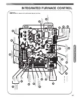
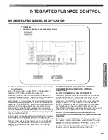
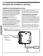
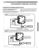
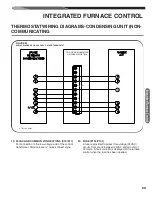
INTEGRATED FURNACE CONTROL
PUSHBUTTON
Note:
In case of active dual faults – e.g. typical for pres-
sure switch faults, where fault
"57"
and
"45"
can be active
and become promoted at the same time – the mechanism
from the previous paragraph can be omitted. IFC can add
new records into the fault history instead of replacing the
existing records if the active dual faults get promoted to
the higher fault level.
Faults older than 168 powered hours will be automatically
deleted from the fault buffer.
When fault recall is activated, the six most recent faults
which have occurred within 1 week (168 powered hours)
will be displayed on the seven segment display in succes-
sion from the most recent to the oldest.
When displaying fault codes stored in the buffer, the con-
trol will flash the A and D segments of the right SSD for
1/2 second to indicate the beginning of the fault recall.
Each fault shall be displayed steady for one second fol-
lowed by energizing the top segment (A or D depending
on the position of the Display Orientation Dipswitch) of the
least significant (right most) Seven-segment display for
1/2 second followed by the next fault displayed for one
second. This cycle repeats until all faults in the buffer are
displayed. After all of the faults are displayed, the control
will again energize the A and D segment of the least signif-
icant S.S.D. for 1/2 second.
Airflow display
Displayed CFM range is between 100 and 9999 per fol-
lowing sequence:
The sequence repeats until the status menu is exited or
the pushbutton is pressed again.
Fire rate display
Gas heat fire rate is displayed for 1 second as follows:
“0”
is displayed when flame is not lit.
Current firing rate = 0% to 99% or HI displayed for 100%
firing rate.
Model BTU Capacity/1000
The furnace input BTU will be taken from the model data.
Values less than 100 will be displayed as two digits (exam-
ple 70 displayed as 70). Values of 100 or greater will be
displayed as three digits. The most significant digit will be
displayed for one second on the left SSD followed by the
remaining two digits which are also displayed for one sec-
ond. Example: 112 would be displayed as 1 followed by 12.
Temperature Rise
Temperature rise is to be displayed as absolute value of
(Supply Temp – Return Temp) clamped at the maximum of
99 degrees F. If the Supply air temp sensor is not avail-
able the category will not be displayed.
Clearing Fault History
The fault buffer can be cleared with the pushbutton while
the Fault History Display (FL) menu is active by holding
down the pushbutton for 5 seconds or more. For indication
that the fault buffer is clear the IFC will flash segments A
and D of the right-most seven segment displays one sec-
ond on and one second off three times after the fault clear
command has been recognized.
Extended Display Mode
If the pushbutton is being pressed during the power-up se-
quence, IFC will turn on the extended display mode. The
extended display mode modifies the display operation per
the following table:
The extended display mode remains active until power
cycle or microprocessor reset.
When fault recall is activated, the six most recent faults which have occurred within 1 week (168
powered hours) will be displayed on the seven segment display in succession from the most recent to
the oldest.
When displaying fault codes stored in the buffer, the control will flash the A and D segments of the right
SSD for ½ second to indicate the beginning of the fault recall. Each fault shall be displayed steady for one
second followed by energizing the top segment (A or D depending on the position of the Display
Orientation Dipswitch) of the least significant (right most) Seven-segment display for ½ second followed
by the next fault displayed for one second. This cycle repeats until all faults in the buffer are displayed.
After all of the faults are displayed, the control will again energize the A and D segment of the least
significant S.S.D. for ½ second.
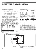
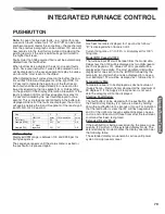
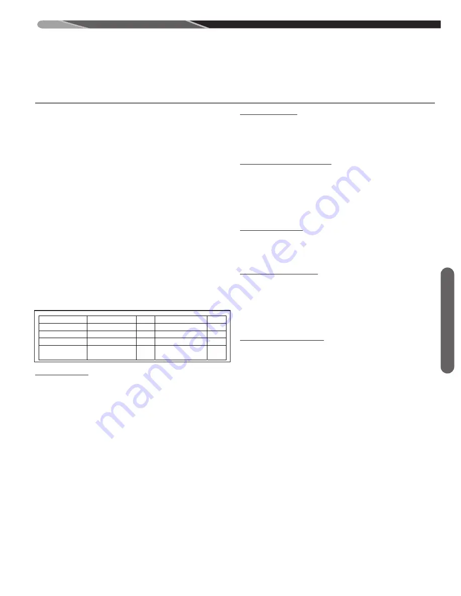
Airflow display
Displayed CFM range is between 100 and 9999 per following sequence:
Step
1
2
3
4
Info CFM/100
delay
CFM modulo 100
delay
Time (secs)
1
0.5
1
2
Example
(1246)
“12”
Off
“46”
Off
Example (721)
“7” (right
segment) Off
“21”
Off
The sequence repeats until the status menu is exited or the pushbutton is pressed again.
Fire rate display
Gas heat fire rate is displayed for 1 second as follows:
“
0
” is displayed when flame is not lit.
Current firing rate = 0% to 99% or HI displayed for 100% firing rate.
Model BTU Capacity/1000
The furnace input BTU will be taken from the model dat. Values less than 100 will be displayed as two
digits (example 70 displayed as 70). Values of 100 or greater will be displayed as three digits. The most
significant digit will be displayed for one second on the left SSD followed by the remaining two digits
which are also displayed for one second. Example: 117 would be displayed as 1 followed by 17.
Temperature Rise
Temperature rise is to be displayed as absolute value of (Supply Temp – Return Temp) clamped at the
maximum of 99 degrees F. If the Supply air temp sensor is not available the category will not be
displayed.
Clearing Fault History
The fault buffer can be cleared with the pushbutton while the Fault History Display (FL) menu is activeby
holding down the pushbutton for 5 seconds or more. For indication that the fault buffer is clear the IFC
will flash segments A and D of the right-most seven segment displays one second on and one second off
three times after the fault clear command has been recognized.
Int
eg
rat
ed
Fu
rn
ace
Co
ntr
ol


