


46
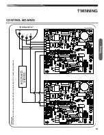
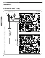
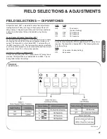
BLOWER SPEED SELECTIONS
The UT Electronic Controls control boards have four quick con-
nect terminals for connecting the motor speed leads. These are:
1. FAN SPEED* — motor runs on this speed when the thermo-
stat is in the “FAN” position.
2. COOL — connect desired cooling speed.
3. HEAT — connect desired heating speed.
4. HEAT/COOL* — connect desired speed when heating and
cooling speed are the same.
5. If heating and continuous speed are the same, jump across
“FAN” and “HEAT” terminals.
See Table 10 for instructions for setting the blower “OFF” timings.
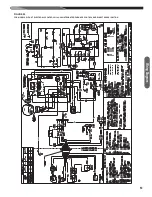
GAS FURNACE (DIRECT DRIVE)
INSTRUCTIONS FOR CHANGING
BLOWER SPEED
The blower motor is wired for blower speeds required for normal
operation as shown.
If additional blower speed taps are available (leads connected to
“M1” and “M2” on the electronic control), speeds may be changed
if necessary to fit requirements of the particular installation. Re-
connect the unused motor leads to “M1” or “M2.” Check motor
lead color for speed designation.
Heating speeds should not be reduced where it could cause the
furnace air temperature to rise to exceed the maximum outlet air
temperature specified for the unit.
!
CAUTION
DO NOT CONNECT ANY MOTOR SPEEDS TO “HEAT” OR
“COOL” IF YOU USE THE “HEAT/COOL” TERMINAL. DOING
SO WILL DAMAGE THE BLOWER MOTOR. UNUSED
MOTOR WIRE TAPS MUST BE CONNECTED TO PARKING
TERMINALS M1 AND M2 OF THE IFC, OR PROPERLY IN-
SULATED.
!
WARNING
DISCONNECT THE ELECTRICAL SUPPLY TO THE FUR-
NACE BEFORE ATTEMPTING TO CHANGE THE BLOWER
SPEED. FAILURE TO DO SO CAN CAUSE ELECTRICAL
SHOCK RESULTING IN SEVERE PERSONAL INJURY OR
DEATH.
Low 894 775 655 595 533 496 462 423 357
Med. Lo 971 912 875 839 804 758 713 684 644
Med. 1117 1081 1051 1024 995 973 938 908 878
Med. Hi 1326 1291 1275 1240 1204 1171 1144 1114 1077
High 1440 1432 1405 1382 1353 1322 1305 1272 1251
Low 1208 1141 1103 1057 1008 966 916 869 818
Med. Lo 1363 1318 1275 1230 1189 1129 1091 1053 1012
Med. 1447 1417 1366 1329 1288 1250 1215 1176 1137
Med. Hi 1553 1521 1478 1444 1407 1372 1332 1295 1264
High 1616 1574 1547 1508 1478 1438 1402 1375 1341
Low 1277 1211 1164 1103 1035 967 861 800 740
Med. Lo 1556 1498 1456 1409 1353 1308 1254 1198 1125
Med. 1644 1597 1554 1511 1463 1400 1358 1304 1253
Med. Hi 1879 1842 1785 1729 1692 1674 1621 1579 1537
High 2071 2025 1992 1948 1902 1872 1840 1795 1750
Low 1398 1338 1278 1232 1177 1130 1041 975 909
Med. Lo 1593 1546 1495 1454 1414 1342 1304 1251 1190
Med. 1878 1844 1807 1753 1714 1675 1634 1578 1536
Med. Hi 2025 1967 1931 1886 1856 1812 1748 1721 1668
High 2165 2124 2082 2047 2012 1973 1934 1894 1859
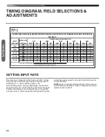
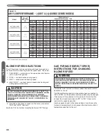
TABLE 12
AIR FLOW PERFORMANCE – (-)801T & (-)(-)80MSX SERIES MODELS
Model
Motor HP
Blower Size
IN.
CFM Air Delivery
External Static Pressure, ” W.C.
Speed Tap
0.1
0.2
0.3
0.4
0.5
0.6
0.7
0.8
0.9
(-)801TA050314MSA
(-)(-)80MSX050A30SA
1/2
11 x 6
(-)801TA075417MSA
(-)(-)80MSX075B40SA
(-)801TA100521MSA
(-)(-)80MSX100C50SA
(-)801TA125524MSA
(-)(-)80MSX125D50SA
1/2
11 x 7
3/4
11 x 10
3/4
11 x 10
NOTE: Shaded data is factory heating tap.
Ai
rfl
ow
Summary of Contents for (-)(-)80MSX050A30SA
Page 52: ...52 CM 0814 ...


