


10
BO
TT
OM
TO
P
LEFT SIDE
FRONT
RIGHT SIDE
G
AS
CO
NNE
CT
I
O
N
ELE
CTR
I
CA
L
CO
NNE
CT
I
O
N
LINE V
O
L
TAG
E
ELE
CTR
I
CA
L
CO
NNE
CT
I
O
N
L
OW
V
O
L
TAG
E
OPT
I
O
N
A
L
GAS
CO
NNE
CT
I
O
N
OPT
I
O
N
A
L L
OW
V
O
L
TAG
E
W
I
R
IN
G
OPT
I
O
N
A
L LINE V
O
L
TAG
E
W
I
R
IN
G
A I R F L O W
RE
TURN AIR
SUPPL
Y
AIR
HO
T
MODEL
A
B
C
D
E
F
RIGH
T SIDE
BACK
TOP
FRON
T
VENT
5
1
4
13 27/32
10 5/8
༃
11 1/2
1
7/8
0
4
༄
01
3
6
༅
85 lbs.
7
17 1/2
16 11/32
12 3/8
༃
15
2 1/2
0
3
༄
01
3
6
༅
105 lbs.
10
21
19 27/32
14 1/8
༃
18 1/2
2
1/2
0
0
0
1
3
6
༅
120 lbs.
12
24 1/2
23 11/32
15 7/8
༃
22
2 1/2
0
0
0
1
3
6
༅
140 lbs.
15
24 1/2
23 11/32
15 7/8
༃
22
2 1/2
0
0
0
1
3
6
༅
150 lbs.
༃
MAY REQUIRE 3
" TO 4" OR 3" TO 5
" ADAPTER.
4" ADAPTER INCLUDED WITH (-)801P UNITS.
༄
MAY BE 0" WITH TYPE B VENT.
༅
MAY BE 1" WITH TYPE B VENT.
LEFT SIDE
REDUCED CL
EARANCE (IN.)
SHIP
WGTS.
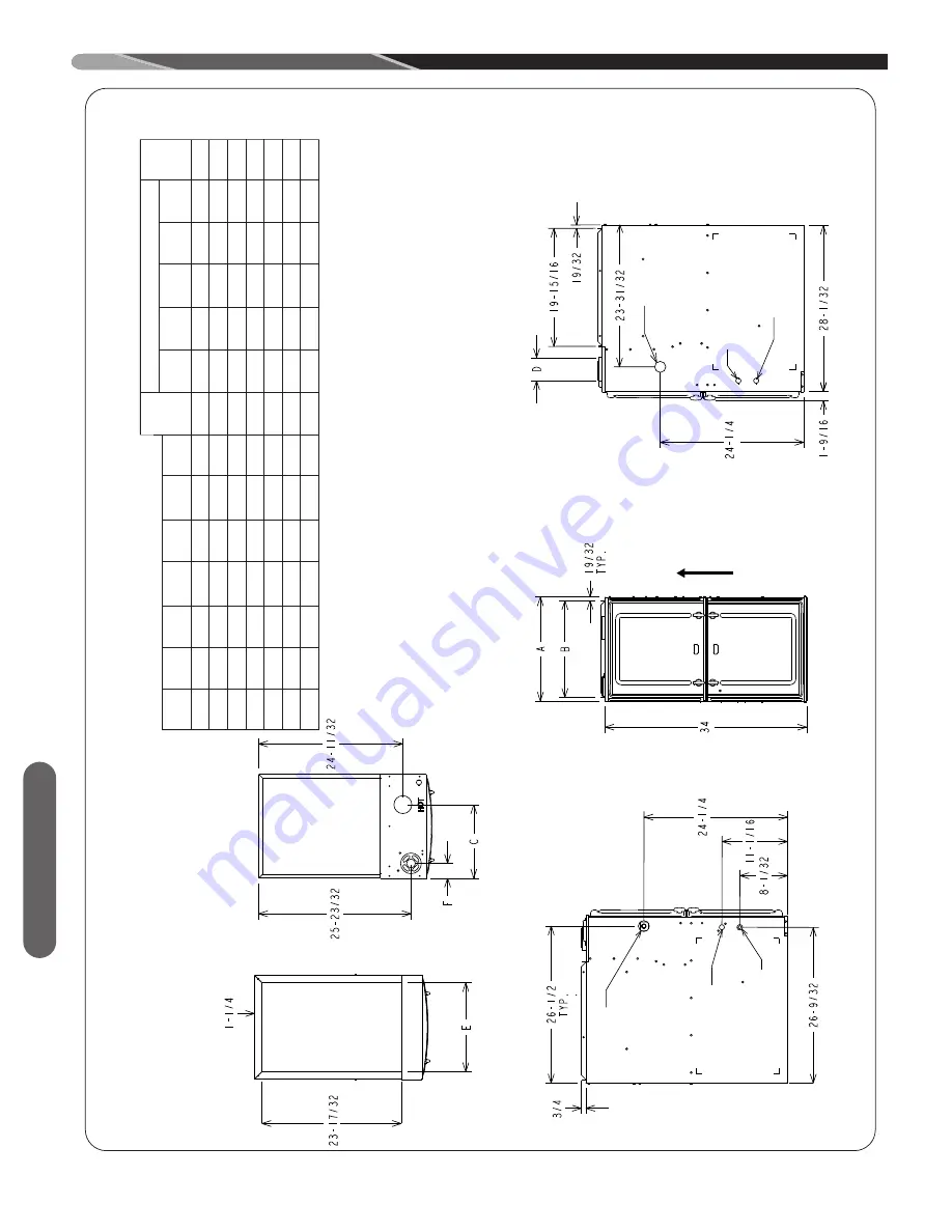
FIGURE 4
UPFLOW/HORIZONTAL DIMENSIONS
Location
ST
-A1220-04
REDUCED CLEARANCE (IN.)
Input
A
B
C
D
E
F
Left
Right
Back
T
o
p
Front
V
ent
Ship.
Side
Side
Wgts.
0
50
14
12
27
/
32
10
5
/
8
➀
11
1
/
2
1
7
/
8
0
4
➁
0
1
3
6
➂
85 lbs.
050
17
1
/
2
16
11
/
32
12
3
/
8
➀
15
2
1
/
2
0
3
➁
0
1
3
6
➂
105 lbs.
075
17
1
/
2
16
11
/
32
12
3
/
8
➀
15
2
1
/
2
0
3
➁
0
1
3
6
➂
105 lbs.
075
21
19
27
/
32
14
1
/
8
➀
18
1
/
2
2
1
/
2
0
0
0
1
3
6
➂
120 lbs.
100
21
19
27
/
32
14
1
/
8
➀
18
1
/
2
2
1
/
2
0
0
0
1
3
6
➂
120 lbs.
125
24
1
/
2
23
11
/
32
15
7
/
8
➀
22
2
1
/
2
0
0
0
1
3
6
➂
140 lbs.
150
24
1
/
2
23
11
/
32
15
7
/
8
➀
22
2
1
/
2
0
0
0
1
3
6
➂
150 lbs.
CLEARANCE
T
O
COMB
USTIBLE MA
TERIAL (INCHES)
UPFLO
W/HORIZONT
A
L MODELS
➀
May require 3” to 4” or 3” or 5” adapter
.
4” adapter optional.
➁
May be 0” with type B vent.
➂
May be 1” with type B vent.
*See furnace spec sheet for model availability
.


