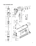
RGN NT65 Operating Manual Download Page 12


12 


PARTS LIST-NT65 

NO. 

CODE 

Description 


NO. 

CODE 

Description 

610170 

BOLT   M6X12 (Loctite) 


38 

420660 

ADJUST BUTTON 

321080 

BUSHING 


39 

630120 

STEEL BALL 

410330 

EXHAUST COVER   


40 

620440 

SPRING 

610210 

BOLT   M6X22 


41 

321000 

TRIGGER 

110240 

CYLINDER CAP 


42 

640040 

ROLL PIN 2.5X16 

410320 

WASHER 


43 

321120 

CONTACT PLATE 

620470 

COMPRESSION SPRING 


44 

640180 

ROLL PIN 3X30 

510450 

O-RING   21.2X2.65 


45 

410140 

HANDLE GRIP 

410310 

HEAD VALVE PISTON 


46 

610100 

BOLT   M5X20 

10 

520170 

GASKET 


47 

110250 

END CAP  

11 

510490 

O-RING   34.5X3.55 


48 

520180 

END CAP SEAL 

12 

310210 

PISTON 


49 

321110 

SLEEVE 

13 

321070 

DRIVER BLADE (Loctite) 


50 

630140 

WASHER 

14 

321060 

WASHER 


51 

620490 

ROLL SPRING 

15 

420680 

BUMPER 


52 

420710 

MAGAZINE FRAME 

16 

310200 

CYLINDER 


53 

420700 

MAGAZINE   

17 

510600 

O-RING   46.2X3.55 


54 

210310 

PUSHER TOE 

18 

510790 

O-RING   61.5X2.65 


55 

620480 

PUSHER SPRING 

19 

110230 

BODY 


56 

640050 

STRAIGHT PIN 

20 

610240 

BOLT   M6X35 (Loctite) 


57 

321100 

MAGAZINE GUIDE 

21 

620460 

SAFETY SPRING 


58 

420690 

PUSHER   

22 

610320 

NUT   M5 (Nylock) 


59 

321090 

STOP LEVER 

23 

320105 

SAFETY  


60 

610080 

BOLT   M5X16 

24 

620450 

SNAP RING 


61 

510380 

O-RING   16X1.8 

25 

321040 

BOLT 


62 

420090 

TRIGGER VALVE CAGE 

26 

420670 

ADJUSTER 


63 

510410 

O-RING   18.3X2.65 

27 

210300 

NOSE 


64 

640250 

STRAIGHT PIN B3X15 

28 

210290 

NOSE COVER (A) 


65 

510180 

O-RING   5.8X1.9 

29 

640220 

ROLL PIN 4X14 


66 

330010 

TRIGGER VALVE BUSHING 

30 

321030 

LOCK SWITCH 


67 

510210 

O-RING   6.3X1.8 

31 

640120 

ROLL PIN 3X18 


68 

510240 

O-RING   8.6X1.9 

32 

210280 

NOSE COVER (B) 


69 

620050 

TRIGGER VALVE SPRING 

33 

321020 

EXTENSION BAR 


70 

320110 

TRIGGER STEM 

34 

410300 

NOSE CAP 


71 

510030 

O-RING   2.5X1.4 

35 

640170 

ROLL PIN 3X28 


72 

420080 

TRIGGER VALVE CAP 

36 

321010 

SAFETY BRACKET 


P1 

D321071 

DRIVER UNIT 

37 

630130 

SNAP RING 6 


P2 

T420091 

TRIGGER VALVE 

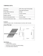
Summary of Contents for NT65

Page 1: ...ly understand the instructions in this manual before operating the pneumatic power tool Carefully read through this OPERATOR S MANUAL to ensure efficient safe operation It is recommended that the Manu...

Page 2: ...ailers are caused by the failure to observe basic safety rules or precautions An accident can often be avoided by recognizing a potentially hazardous situation before it occurs and by observing approp...

Page 3: ...essional training or experience have sufficient expertise in the field of fastener driving tools and sufficient familiarity with relevant governmental industrial protection provisions accident prevent...

Page 4: ...vels which can lead to hearing damage the employer and user should ensure that any necessary hearing protection is provided and used by the operator and others in the work area 3 DO NOT USE ANY POWER...

Page 5: ...henever the air supply is connected to the tool never touch the trigger unless you intend to drive a fastener into the work It is dangerous to walk around carrying the tool with the trigger pulled and...

Page 6: ...may result Do not interfere with the proper operation of the contact trip mechanism 18 WHEN USING THE TOOL OUTSIDE OR ELEVATED PLACE When fastening roofs or similar slanted surface start fastening at...

Page 7: ...agazine capacity 100 nails Maximum allowable pressure 8 3 bar 120psi Recommended pressure range 5 bar to 7 bar 70psi to 100psi Fasteners Only the nail sizes shown in the table below can be driven with...

Page 8: ...ply compressed air to this nailer Moisture or oil in the air compressor may accelerate wear and corrosion in the nailer Drain daily Connections 1 Fittings Install a female coupler to the hose The fema...

Page 9: ...wood are factors in determining what the pressure should be set at Do not exceed this recommended operating pressure NOTE Dirt and water in the air supply are major causes of wear in the tool An air f...

Page 10: ...e of dangerous of hitting the hands or body by mistake Nail loading 1 Disconnect the air hose 2 Insert a strip of DA nail into MAGAZINE 420700 from end slot slide it towards to NOSE 210300 3 Pull PUSH...

Page 11: ...the nailer rail with nailer lubricant Clearing a jam Remove a jammed nail in the following order 1 DISCONNECT AIR HOSE 2 Remove all nails 3 Remove the jammed nail with a slotted head screwdriver 4 In...

Page 12: ...6 2X3 55 54 210310 PUSHER TOE 18 510790 O RING 61 5X2 65 55 620480 PUSHER SPRING 19 110230 BODY 56 640050 STRAIGHT PIN 20 610240 BOLT M6X35 Loctite 57 321100 MAGAZINE GUIDE 21 620460 SAFETY SPRING 58...

Page 13: ...13 TOOL SCHEMATIC NT65...

Page 14: ...14 IMPORTER NOBE ApS Bj dstrupvej 10 DK 8410 R nde Denmark Tel 45 8615 1913 E Mail info nobe dk www nobe dk www rgneurope com 15Ga Angle Finishing Nailer NT65 2016...

Reviews: