


DXP A1616
–
Quick Start
Installation and cabling features
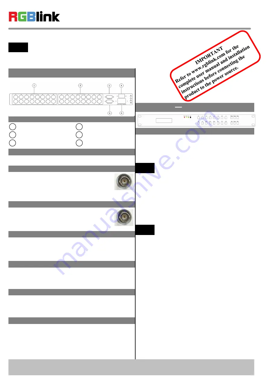
Rear Panel
Connections
1
2
CVBS Output
Step 1-Mounting
Turn off or disconnect all equipment power sources.
Step 4-RS232 In
DXP A1616 Quick Start
Rev 1.0
Page 1 of 3
Address: S603-604 Weiye Building Torch Hi-Tech Industrial Development Zone, Xiamen, Fujian Province, P.R.C
Tel: 00865925771197 Fax:00865925771202
Email: [email protected] http://www.rgblink.cn
CVBS Input
RS232 OUT
4
5
6
Power Switch
Step 3-CVBS Output
VIEW SIZE THE WORLD
NOTE
This guide provides quick start instructions for an experienced installer
to set up and operate the DXP A1616.
For full installation, configuration, and operation details, please refer to
the DXP A1616 user manual, which is available at www.rgblink.com.
3
RS232 IN
Power IEC-3 port
Step 2-CVBS Input
Can receive standard video signal from player,
camera and so on. Standard BNC connector,
support resolution 480i and 576i (PAL, NTSC
and SECAM compatible).
Function Button
Step 5-RS232 Out
Composite output can be gone to composite
monitor or device which can be compatible
with PAL and NTSC standard.
Connecting serial communication interface of RS232
control protocol, can connect central control device,
such as CP 2048.
Serial communication interface of multiple devices
cascading control, can connect many sets of DXP
devices.
Step 6-Power
Plug in power cord which has IEC connector, DXP
A1616 supports AC power from 85 to 264V, 50-60Hz,
which means world wide compatible.
Power On
Push power switch to ON position. LCD module on the
front panel will show RGBLINK and DXP A1616
model information, and go into self verification. For the
first setup, it is default for factory setting. User can
operate DXP A1616 through the menus on LCD panel.
Local Control Front Panel Operation
【
0
】
~
【
9
】
Digital button: selection button for
input and output channel, used to set video signal
input and output channel, also, can be used to number
choice of save or call saving modes.
【
0
】
button can also be used to shut down
the channel output.
NOTE
【
10+
】
,
【
20+
】
,
【
30+
】
+system function button,
means decimal.
NOTE
【
20+
】
can be used as UP arrow keys;
【
30+
】
can be used as DOWN arrow keys.
【
ALL
】
Used as distributor selection, can set a
certain input to all outputs.
【
F1
】
Fast call user save mode 1;
【
F2
】
Fast call user save mode 2;
【
Menu
】
Related menu includes: STATUS, RESET,
MATRIX, LOGO.
【
Mode
】
Audio and video switching key, used to
select 3 modes, such as "Audio and video sync
switching AV", "Audio switching A", "Video
switching V", it is default for "Audio and video sync
switching AV".
【
Enter
】
confirm button, when functional input is
confirm button, and press
【
Enter
】
before enter
menu, it displays the current input/output state, "/"
means empty, and not choose input signal source.
【
20+
】
,
【
30+
】
function reuse button:
Push
【
Menu
】
to enter the menu, press
【
20+
】
UP
arrow keys,
【
30+
】
DOWN arrow keys, and select
the menu option.