Stock Code 873117 en.rgble.com 400-1661-021
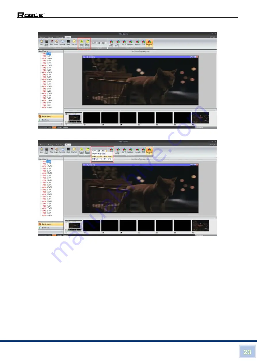
Config file: for users to import or export the configurations
Language selection: At present, there are 3 languages for selections:
COM Config: Users can change the baud rate here accordingly
Page 1: ...Stock Code 873117 en rgble com 400 1661 021 2K 60Hz 8 DVI U inputs and 12 HDMI outputs Video Wall Processor with Preview function VWP 812 User Manual VER 1 0 ...
Page 2: ...e electrical components that may be damaged by electrical spikes surges electric shock lighting strikes etc Use of surge protection systems is highly recommended in order to protect and extend the life of your equipment Table of Contents 1 Introduction 2 2 Features 2 3 Package Contents 2 4 Specifications 3 5 Operation Controls and Functions 4 5 1 Front Panel 4 5 2 Rear Panel 4 6 Device Debugging 4...
Page 3: ...nous output eliminating the asynchronous display between contents of multiple modules 2 Features Supports 8 DVI U inputs Compatible with DVI HDMI VGA CVBS Up to 8 layouts windows in total Colorful LCD screen for the real time information and menu setting Supports sources real time preview function with 1000M LAN port All 60Hz image processing achieving smooth and non tearing images Support output ...
Page 4: ...ort splicing mode of arbitrary form such as 3 4 2 6 etc 8 layouts windows Up to 8 windows or layouts in total Each layout can be freely zoomed and adjusted Images can overlap each other 1000M Preview The signal image can be gained on computer at real time by control software which includes both input signal and output signal Switching Effect When switching signals or user modes users can set up di...
Page 5: ...s LAN 100M LAN 1000M COM serial port POWER Power supply port AC 110 220V 50 60Hz 6 Device Debugging 6 1 Device Connection Device connection could be divided into three parts power connection signal connection and control connection used for software debugging Power connection device power supply Connection method connect power cord to power plug Signal connection the method transferring signal fro...
Page 6: ...ct one crystal head of serial port line which is randomly donated by device with splicer COM port and plug DB9 into computer serial port Any kind of method among the three can realize device software control Connection diagram 6 2 Debugging Steps Step 1 Press MENU to enter into main menu interface and click Splicing Mode to select splicing mode 2 2 2 3 2 4 2 5 2 6 3 2 3 3 3 4 4 2 4 3 5 2 M N ...
Page 7: ...uirement are in consistent Following operations can be taken to set when layout is not in consistent Step 3 Press OK and return to main menu interface select Image parameter and enter into its setting interface to set size and position of each image Note there are two ways for number input 2 2 2 3 2 4 2 5 2 6 3 2 Num in box is PORT OK 2 map INFO view 1 2 3 4 Layout 1 Layout 2 Layout 3 Layout 4 Lay...
Page 8: ...ed to Mode 1 At this point basic device debugging is completed If there is other requirement repeat the operation and save it as other mode After device debugging just recall saved data according to different condition requirements in later stage Data recall is divided into forms 1 For Shortcut key call only select and press the M1 M4 buttons on the front panel which is convenient when mode scenar...
Page 9: ...ced together as a whole one Arrangement of LCD screen Display chart Debugging Steps Step 1 Press MENU and enter into main menu interface to select Cross Mosaic of the first item Device mode Step 2 Press OK to return to main menu interface The large screen splicing is finished select signal source needed to display on screen and click corresponding key s1 s8 3 3 3 4 4 2 4 3 5 2 M N 1 2 3 5 6 7 9 10...
Page 10: ...to Mode 1 and the device can save 32 kinds of modes at most 6 4 Function key Brief explanation of function key INFO Information query key Click this key and enter into its interface showing whether all signal sources are inputting normally Its interface is shown as below Red light means signal is lost while green one shows signal is normal WIN Image key Click this key to enter into its interface a...
Page 11: ...n be adjusted synchronously to meet customers different brightness adjustment requirements for different conditions 2 Output condition Use this button to set black screen or blue screen and then you can switch the output state 3 Special effect switch The device supports directly switching the fade in and fade out effect and ensures that the switching process is without flower screen flash screen o...
Page 12: ...le or mobile 11 Serial port setting Set device serial port like baud rate and etc 12 Output mapping Set splicing mode and output port mapping 6 5 Advanced Menu Language setting Set device language English or Chinese Output resolution Support single output resolution user defined resolution is available and support 30HZ 50HZ and 60HZ frame rate Device default output resolution is 1920 1080 60HZ Fac...
Page 13: ...e The default User name is administrator no password click ok to login and it will show below interface Before getting started please make sure the control PC and controller is connected either by LAN or RS232 cable If using the LAN control the default IP address of the controller is 192 168 0 100 please also make sure the control PC and controller is at the same gateway For using the RS232 please...
Page 14: ...ng the IP control 3 steps to get connected Click Connect Type the IP address 192 168 0 100 then click OK After well connected it will pop up a window for synchronization with the control software click to OK to sync After click OK to sync it will jump to Switching interface ...
Page 15: ...tion lock button 4 Display the details of the User Modes or the Signal sources 5 Collapse for the User Mode or the Signal Source 6 Video Wall Operation area 7 For the local sources preview only with 1000M LAN port can support Device Interface After click Device it will be showing as below For this model we only use the Connect disconnect and Exit two buttons the rest are for other equipment ...
Page 16: ...terface Users can set the video wall configuration accordingly Open new window save or recall user s mode and default back to factory mode and so on function here Screen config and Output Map Screen config for the Video wall number and resolution settings ...
Page 17: ...Stock Code 873117 en rgble com 400 1661 021 Output Map for adjusting the output ports to match with the displays Drag the OUT1 OUT12 up to the Port1 Port12 to replace and adjust ...
Page 18: ...ry Default Echo on off Open Win to open a new window on the Video Wall For open a window it also can be done by pressing and holding left click of the mouse to drag and release on the video wall operation area and users can adjust the window size by moving to the edge of the window ...
Page 19: ...0 1661 021 User Mode For recalling the saved user mode presets total can save 32 presets Save Mode For save the current settings as a user mode preset Factory default Click this one will reset all the parameters as factory default mode ...
Page 20: ... Echo On Turn on the local preview function on the control PC only support with 1000M Port Echo Off Turn off the local preview function on the control PC only support with 1000M Port Screen Control those functions are not available for this mode ...
Page 21: ...ble com 400 1661 021 Tools interface With interface users can add more operation users here with different rights language setting and also change to baud rate and IP address Users management add new users or delete the users ...
Page 22: ...117 en rgble com 400 1661 021 Mode switching effects setting users can set up the switching effects CUT or Fade and time while recall the save user mode The Auto Schedule and Shortcut are not functional on this mode ...
Page 23: ...Stock Code 873117 en rgble com 400 1661 021 Bright Users can adjust the brightness and Contrast of the output Black Users can set up the output video as Black Blue screen if the video not correct ...
Page 24: ...117 en rgble com 400 1661 021 Config file for users to import or export the configurations Language selection At present there are 3 languages for selections COM Config Users can change the baud rate here accordingly ...
Page 25: ...dress of the controller accordingly to the application UI Style Users can set and select the UI style from here Other functions Interfaces On the left side users can find the Signal source Monitor Setting and User Mode icons here With different icons it will show different contents ...
Page 26: ...windows For moving the window users will only need to move the mouse the window then press and hold the left click to move the window For closing the window users either can click the red X to close one by one or right click the mouse to find the close all function ...
Page 27: ...1_02_00_fd_0d_0a Recall mode 3 e9_01_11_03_00_fe_0d_0a Recall mode 4 e9_01_11_04_00_ff_0d_0a Recall mode 5 e9_01_11_05_00_00_0d_0a Recall mode 6 e9_01_11_06_00_01_0d_0a Recall mode 7 e9_01_11_07_00_02_0d_0a Recall mode 8 e9_01_11_08_00_03_0d_0a Recall mode 9 e9_01_11_09_00_04_0d_0a Recall mode 10 e9_01_11_0a_00_05_0d_0a Recall mode 11 e9_01_11_0b_00_06_0d_0a Recall mode 12 e9_01_11_0c_00_07_0d_0a ...
Page 28: ...0d_0a Recall mode 22 e9_01_11_1f_00_11_0d_0a Recall mode 23 e9_01_11_20_00_12_0d_0a Recall mode 24 e9_01_11_21_00_13_0d_0a Recall mode 25 e9_01_11_22_00_14_0d_0a Recall mode 26 e9_01_11_23_00_15_0d_0a Recall mode 27 e9_01_11_24_00_16_0d_0a Recall mode 28 e9_01_11_25_00_17_0d_0a Recall mode 29 e9_01_11_26_00_18_0d_0a Recall mode 30 e9_01_11_27_00_19_0d_0a Recall mode 31 e9_01_11_28_00_1a_0d_0a Reca...