RF-BM-ND08
Shenzhen RF-star Technology Co., Ltd.
Page 9 of 19
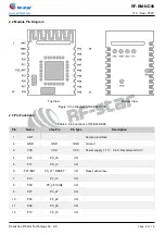
2.2 Module Pin Diagram
Top View Bottom View
Figure 3. Pin Diagram of RF-BM-ND08
2.3 Pin Functions
Table 2. Pin Functions of RF-BM-ND08
Pin
Name
Chip Pin
Pin Type
Description
1
ANT
-
-
Antenna interface
2
GND
GND
GND
Ground
3
VCC
VCC
VCC
Power supply 1.7 V ~ 3.6 V, Recommend 3.3 V
4
P25
P0_25
I/O
5
P17
P0_17
I/O
6
P21/RST
P0_21 / RESET
I/O
Reset, active low.
7
P13
P0_13
I/O
8
P28
P0_28 / AIN4
I/O
9
P27
P0_27
I/O
10
P26
P0_26
I/O
11
P09
P0_09
I/O
12
P10
P0_10
I/O

