


RF-83UP
Shenzhen RF-star Technology Co., Ltd.
Page 8 of 35
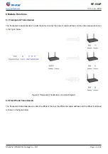
2.2 Module Pin Diagram
Figure 3. Pin Diagram of RF-83UP
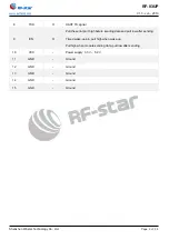
2.3 Pin Functions
Table 2. Pin Functions of RF-83UP
Pin
Name
Pin Type
Description
1
RES_MCU
I
Reset pin, NC.
2
GND
P
Ground, NC.
3
SWIM_MCU
IO
SWIM pin of internal MCU
4
VCC
P
VCC (Power supply pin when flash the firmware)
5
S0
I
Cooperate with S1 to determine the working mode.
(Cannot be NC, need be grounded if not used.)
6
S1
I
Cooperate with S0 to determine the working mode.
(Cannot be NC, need be grounded if not used.)
7
RXD
I
UART RX signal