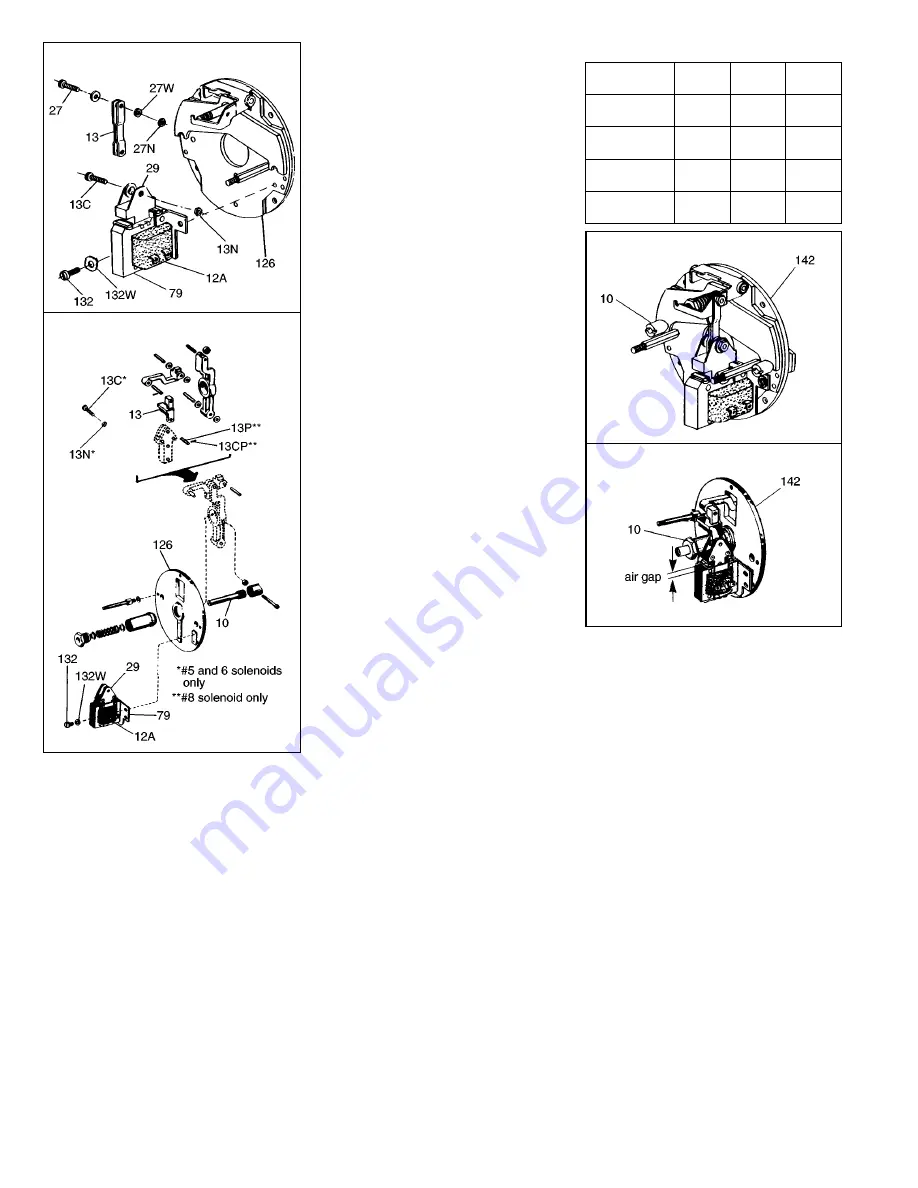
5. For metallic plunger guides (82)
remove plunger guide screw (84).
Remove both plunger guides (82) by
prying up on the flanges.
To remove non-metallic plunger guides
(82), remove screw (84) and lock
washer (84W). Insert shim stock or
other thin gauge material at top center
of coil between coil and solenoid frame.
Push to release lock tab while lifting up
on plunger guide. Repeat for other
guide.
6. Slide coil (12A) out from solenoid
frame (79) in the direction of the coil
terminals. If necessary, tap coil lightly
with a soft hammer. If solenoid coil
had burned out, be sure to remove all
foreign material from the plunger
guides.
7. Install new coil (12A) into solenoid
frame with same relative position as
old coil.
Assemble new non-metallic plunger
guides (82) by inserting into position
and pushing down until lock tab snaps
under top bar of solenoid frame. Install
plunger guide screw and lock washer.
With encapsulated coils (with
terminals) check that lock tabs allow
free movement of plunger. If movement
is restricted, file chamfer on coil at lock
tab areas.
8. a) On the 57,000 Series, or 67,000
and 77,000 Series with No. 5 and
No. 6 solenoids, install new plunger
(29) to link (13) in reverse order of
Step 4, Item a.
b) On the 67,000 and 77,000 Series
with No. 8 solenoid, install new
plunger (29) to link (13) in reverse
order of Step 4, Item b. Use new
cotter pin (not supplied).
9. Slide solenoid frame (79) over new
plunger (29). Attach to support plate
(126) with three new mounting screws
(132) and lock washers (132W). Note
that on the 57,000 brake there is a
10-24 x 3/8” long fillister head screw
required to mount the upper left
hand flange of solenoid. This screw
is provided in the assembly packet.
Before tightening mounting screws,
align the plunger and frame so
that mating surfaces are parallel.
Manually pulling the plunger (29)
down into the sealed position will help
with alignment. (If later there is a
solenoid buzz upon energization, then
a slight realignment may be
necessary).
10. Manually lift solenoid plunger to
maximum travel. Depress and allow
solenoid plunger to snap out several
times. Measure solenoid air gap
between mating surfaces of solenoid
and solenoid plunger. (On vertically
mounted brakes, it will be necessary
to push solenoid plunger into solenoid
frame to the point where spring
pressure is felt, before measuring
solenoid air gap). The correct solenoid
air gap measurements are shown
in Table.
11. Solenoid gap adjustment:
a) 57,000 Series
When gap reaches 3/4” to 7/8”
brake must be adjusted. Turn both
wear adjustment nuts (10) equal
amounts in clockwise direction
(one half turn at a time) until gap
is 1/2” to 5/8”. The screwdriver
slots in both adjustment nuts
must always be on the horizontal
centerline (Figure 4) to permit full
bearing of pressure contact points.
b) 67,000 and 77,000 Series
Insert screwdriver and turn adjusting
stud (10) counterclockwise until proper
solenoid gap is attained. (See Table
and Step 10).
12. Reconnect coil leads.
13. Replace housing and housing nuts or
bolts in reverse order of the
appropriate point in Step 1.
14. Caution! Do not run motor with brake
in manual release position. It is
intended only for emergency manual
movement of the driven load, not as a
substitute for full electrical release.
NOTE: For complete instructions, with
troubleshooting, request sheet
applicable to the series of brake that
you have.
57,000 Series
67,000 and 77,000 Series
Figure 3
Table: Solenoid Air Gap Measurement (in.)
57,000 Series
67,000 and 77,000 Series
Copyright© 1999 by Rexnord Industries, Inc.
Rexnord Industries, Inc., Stearns Division, 5150 S. International Dr., Cudahy, Wisconsin 53110 (414) 272-1100 Fax (414) 277-4364
Nominal Static
Torque (lb-ft)
57,000
Series
67,000
Series
77,000
Series
6
10
1/2-5/8
1/2-5/8
—
7/16
—
7/16
15
25
1/2-5/8
—
7/16
7/16
7/16
7/16
35
50
—
—
9/16
9/16
9/16
9/16
75
105
—
—
5/8
5/8
5/8
5/8


