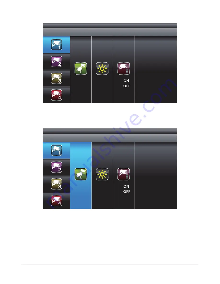
Response QC 3670 Operation Instruction Manual Download Page 18

18

Camera Pairing

With PAIRING section highlighted, press MENU key once to begin camera pairing (pair 
LED on camera will blink once and following with LED blinking continuously indicating 
data transmission in process.

System will confirm pairing process is successful with "PAIRED" displaying on screen.

System will indicate pairing process failed with "PAIRING FAIL" displaying on screen.

Press ESC to return to main menu.

Use▼▲to select the camera to set up (1-4). 
Use◄►to select [PAIRING] [BRIGHTNESS] [CAMERA ON/OFF]

Summary of Contents for QC 3670

Page 1: ...Installation and Operating Instructions These instructions should be retained in a safe place for future reference...

Page 2: ...2...

Page 3: ...5 SYSTEM INTRODUCTION 13 5 1 Icon Functions 13 5 2 System Menu 14 6 System Operation 16 6 1 Camera Setup 16 6 2 Recorder Setup 19 6 3 Event List 21 6 4 System Setup 23 6 5 Alarm Buzzer 26 6 6 Pan Tilt...

Page 4: ...ire regarding local regulations applicable to the lawful installation of video recording surveillance Third party consent may be required WIRELESS DEVICES OPERATING RANGE Ensure the signal reception v...

Page 5: ...The supplied 2GB memory card can be replaced with up to a 32GB capacity one if required NOTE The camera has an open field RF operating range of up to 150m TV Monitor Receiver Front Door Camera 2 Came...

Page 6: ...ce the chances of the cables being tampered with After drilling any hole though an external wall for a cable ensure the hole is sealed up around the cable using a sealant to prevent drafts To prevent...

Page 7: ...Camera and Receiver D 1 x Camera Stands E 1 x Fixings Pack F 1 x Video Playback PC Software CD ROM G 1 x AV Cable for TV Output H I 1 x Camera Antennas 1 x Manual Tools Required Electric drill No 2 Ph...

Page 8: ...nd Fixings Pack Video Playback PC Software CD ROM E F G AV Cable H I Camera Antenna Manual Digital Wireless Receiver Digital Wireless Colour Camera Recordable CCTV Kit CWD3 Installation and Operating...

Page 9: ...WIRELESS RECEIVER Screw the Camera Bracket clockwise on to the lower body of the Camera Turn power on here Video Signal to Input Connect to DC 5V 1A port on Wireless Receiver to Wireless Cammera Conne...

Page 10: ...position again if necessary PROBLEM SOLUTION No camera picture The power supply adaptor for the monitor camera s is not plugged in Camera out o f ra ng e L o cate camera closer to the receiver Poor pi...

Page 11: ...channel of the camera If you are adding another camera to link with the supplied monitor in this kit then ensure its channel is set to a different channel to the existing camera s Follow the steps in...

Page 12: ...5 Camera Installation Attach Stand to Mounting Surface A Secure camera stand on the wall B Loosen the thumb screw C Adjust the camera to the correct viewing position then secure the joint with T bolt...

Page 13: ...ator 2 Power indicator 3 Switch Channel Cursor UP Fast Forward 4 VOL Down Cursor Left VOL Down Switch Display CH 5 Menu OK ENTER PLAY PAUSE 6 VOL Up Cursor Right VOL Up Switch Display CH 7 Switch Chan...

Page 14: ...rding Indicator 4 Audio Channel Indicator 5 Display mode QUAD Display Scan Display 1 Single Display 6 Audio Volume Seven volume levels Full Volume 1 2 Volume Mute 7 Receiver Power Indicator Power indi...

Page 15: ...system will highlight EVENT LIST by default System will idle in MAIN MENU for 2 minutes before exiting MAIN MENU Use to select Press MENU to confirm selection and to enter sub menu CAMERA SETUP RECOR...

Page 16: ...M SETUP ALARM BUZZER PAN TILT ZOOM Press MENU to enter EVENT LIST Press MENU to enter SYSTEM SETUP Press MENU to turn ALARM BUZZER ON OFF for when motion is detected Press MENU to enter single camera...

Page 17: ...S MEMORY CARD OVERWRITE Press MENU to scan activated cameras in full screen mode Press MENU to set memory card overwrite ON or OFF 6 System Operation 6 1 Camera Setup Select CAMERA SETUP press MENU ke...

Page 18: ...ED blinking continuously indicating data transmission in process System will confirm pairing process is successful with PAIRED displaying on screen System will indicate pairing process failed with PAI...

Page 19: ...ith ACTIVATION section highlighted use to enable or disable camera Press ESC to return to main menu NOTE Ensure the cameras are paired to the receiver for SCAN or QUAD to function properly camera ON c...

Page 20: ...TION record audio will automatically switch to the channel triggering by motion Recording cannot be stopped until 30 seconds after recording started This mandatory system operation is designed to prol...

Page 21: ...place inside masked area will be ignored Use to select another grid for setup or press ESC to save and exit Motion Detection Sensitivity Format Memory Card Select RECORDER SETUP press MENU to enter Us...

Page 22: ...xit Use to highlight desired DATE index for playback Press MENU to confirm selection and enter selected folder Press to select Hour each block represent one hour time Press MENU to enter Use to highli...

Page 23: ...2 playback in full screen 1 2 3 4 Channel 3 playback in full screen 1 2 3 4 Channel 4 playback in full screen NOTE 1 For other control functions available during playback mode please refer to section...

Page 24: ...display image scale Use the supplied A V output cable to display the system on a TV monitor if required TV Out System NTSC PAL Select SYSTEM SETUP press MENU to enter Use to highlight DATE AND TIME p...

Page 25: ...hen the display is left idle Select SYSTEM SETUP press MENU to enter Use to select POWER SAVING Use to select SCREEN OFF AFTER 5 MINUTES IDLE SCREEN OFF AFTER 10 MINUTES IDEL SCREEN ALWAYS ON press ME...

Page 26: ...mera ON OFF setting in CAMERA SETUP section will affect which camera s can be displayed during IDLE DISPLAY 2 Audio single channel at anytime will be available during QUAD mode by default on channel 1...

Page 27: ...ORE press MENU to confirm selection and system will restore to factory default Select ALARM BUZZER press MENU to turn buzzer ON or OFF When motion is detected by a camera then a buzzer sound will be t...

Page 28: ...played during IDLE DISPLAY See p 25 for the display inteval setup 2 The system will automatically activate QUAD display if recording function is activated Select PAN TILT ZOOM press MENU once to enter...

Page 29: ...les will appear on display screen a 1 89GB space available on memory card b ERROR either memory card is missing locked or damaged 2 When memory card is full the system will display MEMORY FULL PLEASE...

Page 30: ...orded files without Sec24 Media Player this is for you privacy protection 1 Channel 1 Playback Screen 2 Channel 2 Playback Screen 3 Channel 3 Playback Screen 4 Channel 4 Playback Screen 5 Playback Pro...

Page 31: ...ned by PC for example E In E drive you will find the following icon Please follow installation procedure A to X to complete installation NOTE 1 If Window 7 is running on your PC please right click on...

Page 32: ...32 2 Following error message will appear if user did not select Run as administrator option first before starting the installation A Double click the icon to start installation process...

Page 33: ...33 B Click Next and following window will appear on screen Following window will appear on screen after installation completes Click Finish to complete the installation...

Page 34: ...34 Double click Sec24 Media Player icon on desktop to start software 7 3 Playback Recorded File s...

Page 35: ...35 Click on Load to import and playback previous recorded files SNX files already stored on PC...

Page 36: ...disable audio channel and or video channel s Select Audio to turn off sound Select 1 to turn off video image from channel 1 Select 2 to turn off video image from channel 2 Select 3 to turn off video...

Page 37: ...QUAD SD Card Format Language Default YYYY MM DD HH AM PM MM Go Hour Hour Hour Files NEVER Schedule Scan 5 Sec Scan 10 Sec Scan 15 Sec Channel 1 Channel 2 Channel 3 Channel 4 Activation Pairing Brightn...

Page 38: ...tres in open space Monitor Resolution 800X480 Camera Resolution 640X480 Operating Temperature 10 C 50 C Operating Voltage DC 5V 1A Curren Consumption 550mA max 860mA max Night Vision 5 8m Dimension 13...

Reviews: