Response CWD3 Installation And Operating Instructions Manual Download Page 18

18

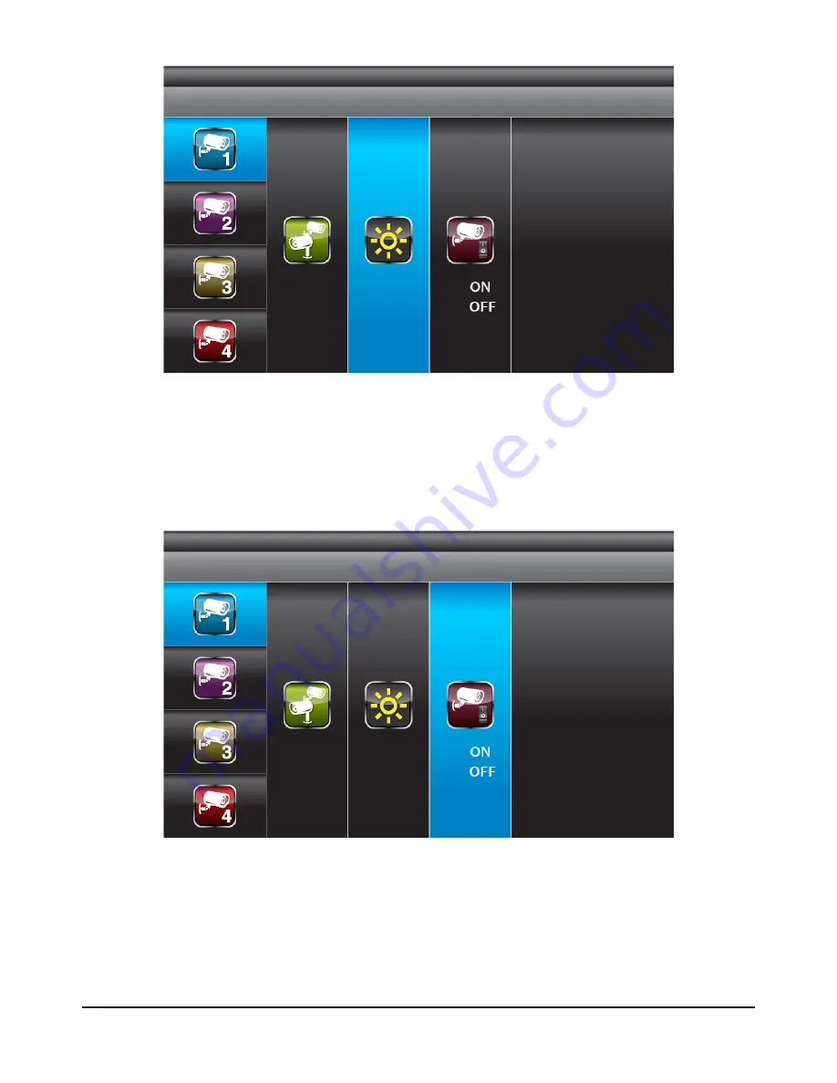
With BRIGHTNESS section highlighted, use ▼▲ to adjust camera brightness.

Press ESC to return to main menu.

With ACTIVATION section highlighted, use ▼▲ to enable or disable camera.

Press ESC to return to main menu.

NOTE:

Ensure the cameras are paired to the receiver for SCAN or QUAD to function 
properly (camera "ON" can only be selected when camera has been paired to 
system.).

Camera Brightness Adjustment

Camera Activation

Summary of Contents for CWD3

Page 1: ...Kit CWD3 Installation and Operating Instructions YOUR HELPLINE 0844 736 9149 www friedland co uk Lines open Monday to Friday 9 00am to 5 00pm Calls charged at local rates These instructions should be...

Page 2: ...Functions 13 5 2 System Menu 14 6 System Operation 16 6 1 Camera Setup 16 6 2 Recorder Setup 19 6 3 Event List 21 6 4 System Setup 23 6 5 Alarm Buzzer 26 6 6 Pan Tilt Zoom 27 6 7 Memory Card Overwrit...

Page 3: ...reception viewed from the wireless camera is the best possible reception i e no interference lines viewed on the TV between the camera and receiver If necessary reduce the distance between the camera...

Page 4: ...om heat sources and high temperature places Avoid direct sunlight Avoid humid places Avoid vibration Install in a ventilated environment The supplied 2GB micro SD memory card can be replaced with up t...

Page 5: ...e the chances of the cables being tampered with After drilling any hole though an external wall for a cable ensure the hole is sealed up around the cable using a sealant to prevent drafts To prevent a...

Page 6: ...cro SD Memory Card and adaptor 1 x Manual 1 x Window Sticker 2 KIT CONTENTS YOUR HELPLINE 0844 736 9149 www friedland co uk Trouble Shooting page 9 or call the Customer Helpline available Monday to Fr...

Page 7: ...36 9149 www friedland co uk Lines open Monday to Friday 9 00am to 5 00pm Calls charged at local rates Digital Wireless Receiver Digital Wireless Colour Camera Recordable CCTV Kit CWD3 Installation and...

Page 8: ...ELESS RECEIVER Turn power on here Video Signal to RCA Input Connect to DC 5V 1A port on Wireless Receiver to Wireless Cammera WIRELESS CAMERA Camera Power Screw the Camera Bracket Screw the Camera Ant...

Page 9: ...nment as it is not weatherproof ON OFF power button Micro SD card slot on 7 LCD DVR Trouble Shooting PROBLEM SOLUTION No camera picture The power supply adaptor for the monitor camera s is not plugged...

Page 10: ...h the supplied monitor in this kit then ensure its channel is set to a different channel to the existing camera s Follow the steps in 6 1 Camera Setup p 16 SETUP section to set or change the channel o...

Page 11: ...5 Camera Installation Attach Stand to Mounting Surface A Secure camera stand on the wall B Loosen the thumb screw C Adjust the camera to the correct viewing position then secure the joint with T bolt...

Page 12: ...wn Cursor Left VOL Down Switch Display CH 5 Menu OK ENTER PLAY PAUSE 6 VOL Up Cursor Right VOL Up Switch Display CH 7 Switch Channel Cursor Down Fast Backward 8 ESC EXIT Previous 9 REC STOP Next STOP...

Page 13: ...7 Monitor Power Indicator Power indicator will indicate 100 when adaptor in use or the battery is fully charged Power indicator will indicate much battery power power available for operation in block...

Page 14: ...system will highlight EVENT LIST by default System will idle in MAIN MENU for 2 minutes before exiting MAIN MENU Use to select Press MENU to confirm selection and to enter sub menu CAMERA SETUP RECOR...

Page 15: ...ENU to enter SYSTEM SETUP Press MENU to turn ALARM BUZZER ON OFF for when motion is detected Press MENU to enter single camera PAN TILT ZOOM mode YOUR HELPLINE 0844 736 9149 www friedland co uk Troubl...

Page 16: ...S MEMORY CARD OVERWRITE Press MENU to scan activated cameras in full screen mode Press MENU to set memory card overwrite ON or OFF 6 System Operation 6 1 Camera Setup Select CAMERA SETUP press MENU ke...

Page 17: ...ED blinking continuously indicating data transmission in process System will confirm pairing process is successful with PAIRED displaying on screen System will indicate pairing process failed with PAI...

Page 18: ...ith ACTIVATION section highlighted use to enable or disable camera Press ESC to return to main menu NOTE Ensure the cameras are paired to the receiver for SCAN or QUAD to function properly camera ON c...

Page 19: ...corded but separate files depending on the recording time for each file setup p21 i e if set to 2 minutes then 60 clips will be recorded in a 2 hour schedule recording slot While the system is perform...

Page 20: ...place inside masked area will be ignored Use to select another grid for setup or press ESC to save and exit Motion Detection Sensitivity Format Memory Card Select RECORDER SETUP press MENU to enter Us...

Page 21: ...m selection and enter selected folder Press to select Hour each block represent one hour time Press MENU to enter Use to highlight desired HOUR for playback Press MENU to confirm selection and enter s...

Page 22: ...playback selected file NOTE By default playback display will be QUAD displaying images of all cameras paired 1 2 3 4 All channel playback For single camera display press MENU once after playback start...

Page 23: ...display image scale TV Out System NTSC PAL Select SYSTEM SETUP press MENU to enter Use to highlight DATE AND TIME press MENU to enter Use to highlight adjust YEAR MONTH DATE HOUR MINUTE use to adjust...

Page 24: ...hen the display is left idle Select SYSTEM SETUP press MENU to enter Use to select POWER SAVING Use to select SCREEN OFF AFTER 5 MINUTES IDLE SCREEN OFF AFTER 10 MINUTES IDEL SCREEN ALWAYS ON press ME...

Page 25: ...n be displayed during IDLE DISPLAY 2 Audio single channel at anytime will be available during QUAD mode by default on channel 1 or the next available channel with camera paired to system single FULL s...

Page 26: ...ORE press MENU to confirm selection and system will restore to factory default Select ALARM BUZZER press MENU to turn buzzer ON or OFF When motion is detected by a camera then a buzzer sound will be t...

Page 27: ...layed during IDLE DISPLAY See p 25 for the display interval setup 2 The system will automatically activate QUAD display if recording function is activated Select PAN TILT ZOOM press MENU once to enter...

Page 28: ...les will appear on display screen a 1 89GB space available on memory card b ERROR either memory card is missing locked or damaged 2 When memory card is full the system will display MEMORY FULL PLEASE...

Page 29: ...creen 3 Channel 3 Playback Screen 4 Channel 4 Playback Screen 5 Playback Progress Bar 6 Play 7 Pause 8 Stop 9 Fast Rewind 10 Fast Forward 11 Load Recorded File s 12 Replay Last File 13 Channel Enable...

Page 30: ...by the PC for example E In this drive you will find the following icon Please read the following steps to complete installation 7 2 1 If Window 7 is running on your PC please right click on icon 2011...

Page 31: ...31 7 2 2 The following error message will appear if you did not select Run as administrator option first before starting the installation 7 2 3 Double click the icon to start installation process...

Page 32: ...32 7 2 4 Click Next and the following window will appear on the screen 7 2 5 The following window will appear on the screen after installation is completed Click Finish to complete the installation...

Page 33: ...Media Player icon on the desktop to start the software 7 3 Playback recorded file s YOUR HELPLINE 0844 736 9149 www friedland co uk Trouble Shooting page 9 or call the Customer Helpline available Mon...

Page 34: ...and playback previous recorded files SNX files already stored on your PC NOTE You will first need to save the files from the Micro SD card to the PC first If your PC has a memory card reader then use...

Page 35: ...disable audio channel and or video channel s Select Audio to turn off sound Select 1 to turn off video image from channel 1 Select 2 to turn off video image from channel 2 Select 3 to turn off video...

Page 36: ...Hour Files NEVER Schedule Scan 5 Sec Scan 10 Sec Scan 15 Sec Channel 1 Channel 2 Channel 3 Channel 4 Activation Pairing Brightness Camera Setup Motion sensitivity Cam1 Cam2 Cam3 Cam4 Record Time 2 min...

Page 37: ...5V 1A Curren Consumption 550mA max 860mA max Night Vision 5 8m Dimension 123x65x65 mm 200x122x25 mm Battery N A 3 7V 1800mAH LI ON Micro SD Card Capacity 640 x 480 VGA 1G 200 Minutes 2G 400 Minutes 8...

Page 38: ...rectify dismantle or alter the product in any way the guarantee will be invalidated The guarantee states Novar ED S entire liability It does not extent to cover consequential loss or damage or install...

Reviews: