background image

English 


Users- & Installation Instruction Cooker Hoods


fi160630aomNEG 

GB 


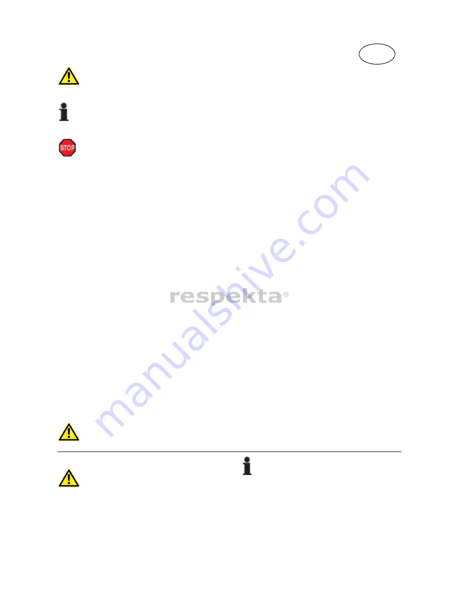
This is a warning symbol 


This is to be found with descriptions of actions where special care is necessary to prevent damage to appliances. 
Pass this safety information on to all users of the appliances. 


This  symbol  refers  to  useful  hints  and  tips 

and  draws  your  attention  to  the  correct  procedure  and 

behaviour. Compliance with the information marked with this symbol will spare you many problems. 

 Warning 

There is a fire risk if cleaning is not carried out in accordance with the instructions.

The air must not be discharged into a flue that is used for exhausting fumes from appliances burning gas or
other fuels (not applicable to appliances that only discharge the air back into the room)

Regulations concerning the discharge of air have to be fulfilled.

When the range hood and appliances supplied with energy other than electricity are simultaneously in
operation, the negative pressure in the room must not exceed 4 Pa (4 x 10

-5 

bar).

Cooker hoods are not intended for use by persons (including children) with reduced physical, sensory or
mental capabilities, or lack of experience and knowledge, unless they have been given supervision or
instruction concerning use of the appliance by a person responsible for their safety.

Children should be supervised to ensure that they do not play with the appliance.

Keep your children from using the cooker hood.

Your cooker hood is for domestic use only, not suitable for barbecue, roast shop and other commercial use.

If the supply cord is damaged, it must be replaced by the manufacturer, its service agent or similarly qualified
persons in order to avoid a hazard.

There shall be adequate ventilation of the room when the range hood is used at the same time as appliances
burning gas or other fuels (not applicable to appliances that only discharge the air back into the room);

Any installation work must be carried out by a qualified electrician or competent person.

The cooker hood and its filter mesh should be cleaned regularly in order to keep in good working order.

Before cleaning, always ensure that you have switched your cooker hood off.

Clean the cooker hood according to the instruction manual and keep the cooker hood from the danger of
burning.

Do not flame under the range hood;

lf there is any fault with your cooker hood, please call the service department appointed by agent for servicing.

Please keep the room draughty when your cooker hood and gas hob are working.

Do not exhaust the gas from cooker hood through the same heated flue which is for the gas from gas hob and
other kitchen appliances.

Before installation and usage, read all the instructions and make sure that the voltage (V) and the frequency
(Hz) indicated on your cooker hood are exactly the same as the voltage (V) and the frequency (Hz) in your
home.

ln order to get the most out of your cooker hood, please read the instruction manual before installing and
using, and keep it in a safe place.

Ensure that you could get our Guaranty for your cooker hood, please provide the warranty card and purchase
receipt, or the Guaranty will not be offered.

  CAUTION:  Accessible parts may become hot when used with cooking appliances. 

2. Intended use


The appliance is intended for domestic use. 

The  manufacturer  is  not  responsible  for  damage 
resulting from improper use or maloperation.


 Extractor hoods remove unpleasant odours and 

vapours and create a pleasant room atmosphere. 
Particles  of  grease,  steam  and  also  moisture  are 
absorbed by the grease filter. 

Summary of Contents for CH 3100 GISA

Page 1: ...l Dunstabzugshauben Installation User s manual Island Cooker hoods CH 44099 GISA CH 3100 GISA CS90IX A N2T1L CLZ90IX A N2P1L NEG Novex Großhandelsgesellschaft für Elektro und Haustechnik GmbH Chenover Str 5 D 67117 Limburgerhof fi160630aomNEG D GB ...

Page 2: ... GHP 6FKXW GHV HQXW HUV XQG GHP HUlW GLHQHQ XQG HLQHP DNWXHOOHQ WHFKQLVFKHQ 6WDQGDUG HQWVSUHFKHQ 6ROOWHQ 6LH WURW XQVHUHU HLQJHKHQGHQ 4XDOLWlWVNRQWUROOH HLQPDO HWZDV X EHDQVWDQGHQ KDEHQ VR ZHQGHQ 6LH VLFK ELWWH DQ GHQ XQGHQGLHQVW LHVHU ZLUG KQHQ JHUQH ZHLWHUKHOIHQ RQIRUPLWlWVHUNOlUXQJ HU HUVWHOOHU GHU GHV KLHULQ EHVFKULHEHQHQ 3URGXNWH V DXI ZHOFKH V VLFK GLHVH UNOlUXQJ EH LHKW HUNOlUW KLHUPLW LQ D...

Page 3: ...FK UHGX LHUHQ VLFK GLH DUDQWLH XQG HZlKUOHLVWXQJ XP 1 Hinweis Symbol Erklärung LHVHV 6 PERO DXI GHP 3URGXNW RGHU VHLQHU 9HUSDFNXQJ ZHLVW GDUDXI KLQ GDVV GLHVHV 3URGXNW QLFKW DOV QRUPDOHU DXVKDOWVDEIDOO X EHKDQGHOQ LVW VRQGHUQ DQ HLQHP 6DPPHOSXQNW I U GDV 5HF FOLQJ YRQ HOHNWULVFKHQ XQG HOHNWURQLVFKHQ HUlWHQ DEJHJHEHQ ZHUGHQ PXVV XUFK KUHQ HLWUDJ XP NRUUHNWHQ QWVRUJHQ GLHVHV 3URGXNWV VFK W HQ 6LH GL...

Page 4: ...EOXIWVFKDFKW QDFK DXVVHQ YHUOHJW ZHUGHQ U GDUI GXUFK NHLQH DQGHUH 6FKlFKWH RGHU DPLQH YHUOHJW ZHUGHQ x HVHQ 6LH GLH HGLHQXQJVDQOHLWXQJ 0RQWDJHDQOHLWXQJ YRU GHU 0RQWDJH GHV HUlWV JU QGOLFK GXUFK x 3U IHQ 6LH RE GLH 7HFKQLVFKHQ DWHQ 9 XQG DXI GHP 7 SHQVFKLOG GHV HUlWV PLW GHQHQ KUHU DXVLQVWDOODWLRQ EHUHLQVWLPPHQ 6WLPPHQ GLHVH QLFKW EHUHLQ EULQJHQ 6LH GDV HUlW DQ GLH 9HUNDXIVVWHOOH XU FN HL GLHVEH JO...

Page 5: ...NWULVFKH QVFKOXVV XQG GLH 9HUELQGXQJHQ GHU E XJVOHLWXQJHQ PXVV XQWHU HDFKWXQJ GHU HUVWHOOHUYRUVFKULIWHQ XQG XQWHU LQKDOWXQJ GHU UWOLFKHQ 9RUVFKULIWHQ YRQ HLQHU DXVJHZLHVHQHQ DFKNUDIW DXVJHI KUW ZHUGHQ HQXW XQJ GHU XQVWDE XJVKDXEH 6LFKHUKHLWVKLQZHLVH XP HEUDXFK lKUHQG GHV HWULHEHV GHU XQVWDE XJVKDXEH P VVHQ GLH HWWILOWHU LPPHU HLQJHVHW W VHLQ DQVRQVWHQ NDQQ VLFK HWWGXQVW LQ GHU DXEH XQG LP EOXIWV V...

Page 6: ...P HUlW YRUKDQGHQHQ HWWILOWHU VLQG UHJHOPlVVLJ X UHLQLJHQ E Z X HUVHW HQ HWWJHVlWWLJWH LOWHU N QQHQ VFKQHOO HXHU IDQJHQ XQG YHUEUHLWHQ XGHP XQDQJHQHKPH HU FKH x 0LW 6FKPXW SDUWLNHOQ XJHVHW WH HWWILOWHU N QQHQ GLH XQNWLRQ GHV HUlWV VWDUN EHHLQWUlFKWLJW x P HUHLFK GHU HGLHQHOHPHQWH QLFKW X IHXFKW UHLQLJHQ XP HLQ LQGULQJHQ YRQ 1lVVH LQ GLH OHNWURQLN X YHUPHLGHQ HVRQGHUH LQZHLVH I U HUlWH PLW GHOVWDKOJ...

Page 7: ...HQ XVWDXVFK RGHU GLH 5HLQLJXQJ GHU LOWHU EHVWHKW UDQGJHIDKU XVZHFKVHOQ GHU DPSHQ FKWHQ 6LH EHLP XVZHFKVHOQ HLQHU DPSH GDUDXI GDVV GLH QHXH DPSH NHLQH K KHUH DWWOHLVWXQJ DOV GLH 2ULJLQDOODPSH KUHV HUlWV KDW DOOV GHU HUlWHGRNXPHQWDWLRQ NHLQH QOHLWXQJ XP XVZHFKVHOQ YRQ DPSHQ EHLOLHJW P VVHQ 6LH GLH DPSH DXV 6LFKHUKHLWVJU QGHQ GXUFK GHQ XQGHQGLHQVW HUVHW HQ ODVVHQ 6LHKH DXFK DSLWHO XQGHQGLHQVW 6W UXQJ...

Page 8: ...XQJHQ VLQG PLW HLQHP XQVWVWRIIGHFNHO YHUVHKHQ LHVHU XQVWVWRIIGHFNHO NDQQ GXUFK UHKHQ LP HJHQXKU HLJHUVLQQ HLQIDFK HQWIHUQW XQG ZDKOZHLVH DXI HLQHU DQGHUHQ QLFKW EHQ WLJWHQ E XJ IIQXQJ PRQWLHUW ZHUGHQ QVWDOODWLRQVDQJDEHQ 0LQGHVWDEVWDQG 8QWHUNDQWH DXEHQN USHU X ODVNHUDPLN XQG XVVNRFKSODWWHQ FP X DVNRFKIHOG FP X RKOH gO RO IHXHUXQJ FP 6FKOLHVVHQ 6LH GDV HUlW HUVW GDQQ DQ GDV 6WURPQHW DQ ZHQQ HV RUGQX...

Page 9: ...ZHUGHQ V N QQWH VRQVW RQGHQVZDVVHU LQ GHQ 0RWRU GHU E XJVKDXEH ODXIHQ x LUG GLH EOXIW LQ HLQHQ EOXIWNDQDO JHI KUW PXVV GDV QGH GHV LQI KUXQJVVWXW HQV LQ 6WU PXQJVULFKWXQJ JHOHQNW ZHUGHQ x LUG GLH EOXIWOHLWXQJ GXUFK N KOH 5lXPH DFKE GHQ XVZ YHUOHJW NDQQ HLQ VWDUNHV 7HPSHUDWXUJHIlOOH LQQHUKDOE GHU HLQ HOQHQ HLWXQJVEHUHLFKH DXIWUHWHQ V LVW GDKHU PLW 6FKZLW RGHU RQGHQVZDVVHU X UHFKQHQ LHV PDFKW HLQH V...

Page 10: ...rations Zwecken Achten Sie beim Zusammenbau darauf dass die Umluftgitter L am Teleskopschacht oben sind wenn die Haube im Umluft Modus betrieben werden soll Deutsch Bedienungs Gebrauchsanleitung Dunstabzugshauben 14 GERÄTEKOMPONENTEN INSELHAUBEN Die Pfeile zeigen die Position und Anzahl Schrauben für den Zusammenbau an Die Pfeile zeigen die Position und Anzahl Schrauben für die Befestigung des Mot...

Page 11: ...tivkohlefilter 2 und 3 am Motor 1 montieren Umschaltung von Abluft auf Umluftbetrieb Deutsch Bedienungs Gebrauchsanleitung Dunstabzugshauben Tasten und Schalterfunktionen 15 GERÄTEBEDIENUNG Inselhauben 15 Minuten Nachlauf Timer Motor EIN AUS Taste A 3 Sekunden gedrückt halten Zahlen 1 3 im Display F blinken Motor schaltet nach 15 Min ab E Gewisse Modelle schalten automatisch auf Umluftbetrieb wenn...

Page 12: ...t Motor läuft nicht Nebst obigen Ursachen sind folgende möglich Ölspuren 16 Problembehbung Lampen defekt Kein Strom Gerätekabel nicht richtig angeschlossen Einwegventil undicht mögliche Ursache Beleuchtung ist an aber Motor läuft nicht Lüftungsklappe blockiert Kondensator defekt Motorlager defekt klemmt Motor riecht verdächtig Gerät ist instabil Befestigungsschrauben nicht fest angezogen Gerät vib...

Page 13: ...die Schraubenlöcher sowie allenfalls den Schlauchausschnitt B Fig 2 an der Decke anzeichnen 2 Die an der Decke angezeichneten Löcher bohren und die Dübel für die Befestigung der Montageplatte setzen Für eine sichere Befestigung der Montageplatte müssen alle dafür vorgesehenen 6 X 40 mm Flachkopfschrauben verwendet werden 3 Den Bohrstaub und allfälligen Bauschutt gründlich entfernen 4 Den Abluftsch...

Page 14: ...ich ist 11 Den Abluftstutzen A Fig 8 mit 4 Stk 8 mm Flachkopfschrauben auf das Motorgehäuse B Fig 8 montieren Wenn die Haube mit einem obenliegenden Glasschirm ausgestattet ist diese von oben über das Motorgehäuse schieben so dass die Löcher im Glasschirm mit den Schraubenlöchern C Fig 8 in der Haube übereinstimmen Dann den Glasschirm mit 4 Schrauben an der Haube befestigen 12 Die komplettierte Ha...

Page 15: ...e manufacturer reserves the right to make any necessary model changes to device types to improve user friendliness and to protect the user and the device and which comply with current technical standards Despite our ongoing quality control should you wish to make a complaint please contact Customer Service They will be pleased to assist EC Declaration of conformity The manufacturer of the product ...

Page 16: ...t service if properly operated and maintained Our appliances are not intended for commercial usage They are designed only for domestic use The warranty and its provisions are reduced by 50 in the case of commercial usage 1 Explanation of information symbols This symbol on the product or its packaging indicates that this product is not to be treated as normal domestic waste but must be disposed of ...

Page 17: ... avoid a hazard There shall be adequate ventilation of the room when the range hood is used at the same time as appliances burning gas or other fuels not applicable to appliances that only discharge the air back into the room Any installation work must be carried out by a qualified electrician or competent person The cooker hood and its filter mesh should be cleaned regularly in order to keep in g...

Page 18: ...her with other non electrically operated appliances the room partial vacuum must not exceed 4 Pa 4 x 10 5 bar g Make sure that the room is adequately ventilated h Regularly clean encrusted food from appliance surfaces i Regularly clean or replace the filter The exhaust air hose must not be made from or contain flammable materials 5 Before using the hood Ensure that the hood has not suffered damage...

Page 19: ...d to discolouring Non compliance with the maintenance and cleaning instructions can result in a fire hazard due to grease deposits The grease filters on your appliance are to be cleaned or replaced at regular intervals Filters saturated with grease can quickly catch fire and also distribute unpleasant odours Grease filters obstructed by dirt particles seriously impair the appliance function When c...

Page 20: ...have a higher wattage than that of the original If the documentation of the cooker hood does not include an instruction for replacing lamps the lamp must be replaced by the customer service for safety reasons See also chapter Customer Service 9 Fault what to do if The motor fails to function Is the plug properly inserted in the socket Is there a power supply failure Has a fuse blown The hood capac...

Page 21: ... cooking hobs 65 cm to gas hob 70 cm to hobs with coal oil wood firing 85 cm Only connect the appliance to the power supply once it is properly installed 11 2 Using the extractor hood as an exhaust air hood with air extracted to outdoors If the extractor hood has been fitted at the factory with a carbon filter this must be removed It is only practicable to use this when operating your hood in circ...

Page 22: ...tor hood motor If the exhaust air is directed into an exhaust air duct the end of the entry fitting must be directed in the direction of flow If the exhaust air pipeline is routed though cool rooms lofts etc there can be a large temperature drop within the individual parts of the pipeline resulting in sweating or condensation water production This renders outlet pipeline insulation necessary In so...

Page 23: ...ures are for Illistration porposes only English Users Installation Instruction Cooker Hoods 14 COMPONENTS OF THE APPLIANCE The arrows indicate the position and number of screws for assembly Arrows indicate the position and number of screws for fixing the motor on the frame When assembling ensure that the exhaust grills L are on the top of the telescopic shaft when the hood is to be operated in rec...

Page 24: ...lighting ON OFF CHANGEOVER TO RECIRCULATION AIR Certain models automatically switch to recirculation mode when the carbon filter is mounted on the motor For the other models proceed as described here below Switch the switching lever C to the desired operation mode English Users Installation Instruction Cooker Hoods 15 APPLIANCE OPPERATING Key Switch functions Island Cooker hoods E 15 Min Motor pow...

Page 25: ...er hoods The internal with of motor off or a bad smell from the motor Beside the above mentioned check the following Replace lights Connect the wires as per the electric diagram Cause The leaf blocked The capacitor damaged The motor jammed bearing Tighten the hanging screw and make it horizontal Tighten the hanging screw and make it horizontal English Users Installation Instruction Cooker Hoods Li...

Page 26: ...Fig 2 against the wall at the appropriate location and mark on the ceiling the screw holes and where necessary the hose section B Fig 2 2 Drill the holes marked on the wall and insert the plugs for fixing the mounting plate For secure fixing of the mounting plate use all the 6 x 40 mm flat head screws supplied 3 Make sure the area is absolutely free from drilling dust and building waste 4 Mount th...

Page 27: ...quent mounting steps 11 Mount the exhaust air connector A Fig 8 with ea 4 8 mm flat head screws on the motor housing B Fig 8 If the hood is fitted with a top glass screen push this over the motor housing from above so that the holes in the glass screen line up with the screw holes C Fig 8 in the hood Then fix the glass screen to the hood with 4 screws 12 Push the assembled hood into the angle bar ...

Reviews: