


© RESOL 11294 flo
wsol_d_d_he
.monen.ind
d
FlowSol D / D HE
19 |
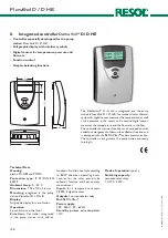
Speed control
Min. speed
adjustment range (10) 30 ... 100%
factory setting (10) 30 %
D
Tset
adjustment range 2 ... 50 K
factory setting 10 K
rise
adjustment range 1 ... 20 K
factory setting 2 K
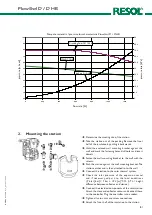
The relay is a semiconductor relay for pump speed control
of standard pumps. Relative pump speed is adapted in 10 %
steps to the current temperature difference between flow
and return. The parameter "
D
Tset“ is used as a set value
for pump speed control. Flow and return sensors are used
as reference sensors. The parameter „rise“ determines at
which change of temperature difference the speed will be
increased. In some cases, it is necessary to increase the
factory setting of the minimum pump speed (30%).
Furthermore, the controller keeps the flow rate within the
flow range of the station.
The
FlowSol
D HE with the high-efficiency pump controls
the pump speed down to 10% via the PWM output.
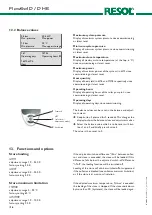
Defective sensors are shown in the status display. In the
next menu, the fault is indicated. For this purpose, briefly
press button 2.
Defective sensors
1,8 bar
Pressure
500 l/h
Flow rate
18,4 kW
Power
Error
S2 defect
P
V
broken
78,6 °C
92°C
34,5 °C
80%
broken
The defective sensor is indicated:
If the cable of a temperature sensor is broken, „broken“
is displayed, if the cable of a temperature sensor is short-
circuited, „short“ is displayed.
If a digital sensor is defective, „Defect“ is displayed.
14. Messages
D
T-overrun function
D
T-overrun
selection „Yes“, „No“
factory setting „No“
off at
adjustment range 0,0 ... 20,0 K
factory setting 5 K
By means of this function, the pump continues to heat the
store even if the switch-off difference between collector
and store has been reached. The pump switches off, if the
adjusted "
D
T-overrun difference“ between flow and return
sensor has been underrun.
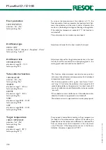
In this menu, the relay can be set into different modes:
• Off
• Auto
• Min. (minimum speed)
• Max. (maximum speed)
If "Off", "Min." or "Max." is selected, the
symbol will be
shown on the status display.
Relay mode
Relay mode
selection „Off“, „Auto“, „Min.“, „Max.“
factory setting „Auto“
1,8 bar
Pressure
500 l/h
Flow rate
18,4 kW
Power
Error
S2 defect
P
V
In the case of an error, a message is shown in the status
display. If there are several messages, only the message
having the highest priority is shown in the status display. All
other recently detected errors and messages respectively
are listed above the balance values (keep button 3 pressed
for 2 seconds).


