


V8205, VR8205 DIRECT IGNITION COMBINATION GAS CONTROLS
7
69-0329—05
1.
Turn off gas supply.
2.
Set the thermostat or controller above room tem-
perature to call for heat.
3.
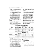
Watch for ignition spark or for glow at hot surface
igniter either immediately or following prepurge.
See DI module specifications.
4.
Time length of igniter operation. See DI module
specifications.
5.
After the module locks out, open manual gas cock
and make sure no gas is flowing to burner.
6.
Set the thermostat below room temperature and
wait one minute.
7.
Operate system through one complete cycle to
make sure all controls operate properly.
Service
WARNING
Fire or Explosion Hazard
Can cause property damage, severe injury, or
death.
Do not disassemble the gas control; it contains
no replaceable components. Attempted
disassembly or repair can damage the gas
control.
CAUTION
Do not apply a jumper across (or short) the valve
coil terminals, even temporarily. Doing so can
burn out the heat anticipator in the thermostat or
damage the DI module.
If Main Burner Will not Come On with Call
for Heat
1.
Make sure the gas control knob is in the ON posi-
tion.
2.
Adjust the thermostat several degrees above room
temperature.
3.
Using an ac voltmeter, check for voltage across MV
terminals at gas control.
4.
If voltage is not present, check control circuit for
proper operation.
5.
If proper control circuit voltage is present, replace
gas control.
Instructions To The Homeowner (For
Your Safety, Read Before Lighting)
WARNING
Fire or Explosion Hazard
If you do not follow the warnings below and the
lighting instructions exactly, a fire or explosion
can result with property damage, personal injury
or loss of life.
1. Before lighting, smell around the appliance
area for gas. If the appliance uses LP (bottled)
gas, be sure to smell next to the floor because
LP gas is heavier than air. If you smell gas,
immediately shut off the manual valve in the
gas piping to the appliance or, on LP, at the
tank. Do not try to light any appliance. Do not
touch any electrical switch or use the
phone. Leave the building and call your gas
supplier. If your gas supplier cannot be
reached, call the fire department.
2. Do not force the gas control knob on the appli-
ance. Use only your hand to turn the gas con-
trol knob. Never use any tools. If the knob will
not operate by hand, replace the control using
a qualified service technician. Force or
attempted repair may result in fire or explosion.
3. The gas control must be replaced if it has been
flooded with water. Call a qualified service
technician.
4. The gas control is a safety device. It must be
re-placed in case of any physical damage such
as bent terminals, missing or broken parts,
stripped threads, or evidence of exposure to
heat.
IMPORTANT:
Follow the operating instructions provided by
the manufacturer of your heating appliance. The
information below will be of assistance in a typ-
ical control application, but the specific controls
used and the procedures outlined by the manu-
fac-turer of your appliance may differ, and
require spe-cial instructions.
To Turn On Furnace
STOP: Read the safety information above
1.
The lighting sequence on this appliance is auto-
matic;
Do not attempt to manually light the main
burner.
2.
If the furnace does not come on when the thermo-
stat is set several degrees above room tempera-
ture, set the thermostat to the bottom of its range
to reset safety control.
3.
Remove burner access panel if provided on your
appliance.
4.
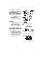
Turn the gas control knob (Fig. 4) clockwise
to
OFF.
5.
Wait five minutes to allow any gas in the combus-
tion chamber to vent. If you smell gas in the appli-
ance area or near the floor in an LP installation,
immediately shut off the manual valve in the gas
piping to the appliance or, on LP, at the tank. Don’t
touch any electrical switch or use the phone. Leave
the building and call your gas supplier. If your gas
supplier cannot be reached, call the fire depart-
ment. Failure to do so may result in fire or explo-
sion.


