SPECIFICATIONS
Capacity
VA
800VA 1000VA
Voltage
100VAC, 110VAC, 120VAC, 220VAC, 230VAC or 240VAC
±
25%
Input
Frequency
50Hz or 60Hz
±
5%
Voltage (Batt. Mode)
100VAC, 110VAC, 120VAC, 220VAC, 230VAC or 240VAC
±
10%,
Frequency
50Hz or 60Hz
±
1Hz
Waveform
Modified sine wave
Output
Transfer Time
Less than 4ms (typical)
Battery Type
Sealed, maintenance-free lead acid batteries with 3-5
years typical lifetime
Battery
Recharge Time
5 hours to 90% of full capacity
Indicator
LED
LED indicator for line on, battery back-up, UPS cut-off
Battery Back-up
Sounding every 3 seconds
Battery Low
Sounding every 1 second
Alarm
Overload
Continue beeping sound
Overload
Fuse & current limited
Short Circuit
Fuse & current limited & cut-off
Protection
Batt. Low Cut-off
No battery drain after cut-off
Physical
Dimension, D*W*H
385*94*170 mm
Operating Temperature
32
℉
-104
℉
at full load, 0~90% relative humidity
(non-condensing)
Environment
Noise Level
Less than 40db (at 1 meter)
Contact Closure
DB9 connector for connecting with Rups-2000 software
Interface
Software
Rups-2000 (Option)
- 10 -
SYSTEM CONCEPT
The purpose to present this chapter is to give you more precise conception
about how UPS works..
1. Block Diagram
AVR.
INV.
CHA.
N.F.
N.F.
INPUT
OUTPUT
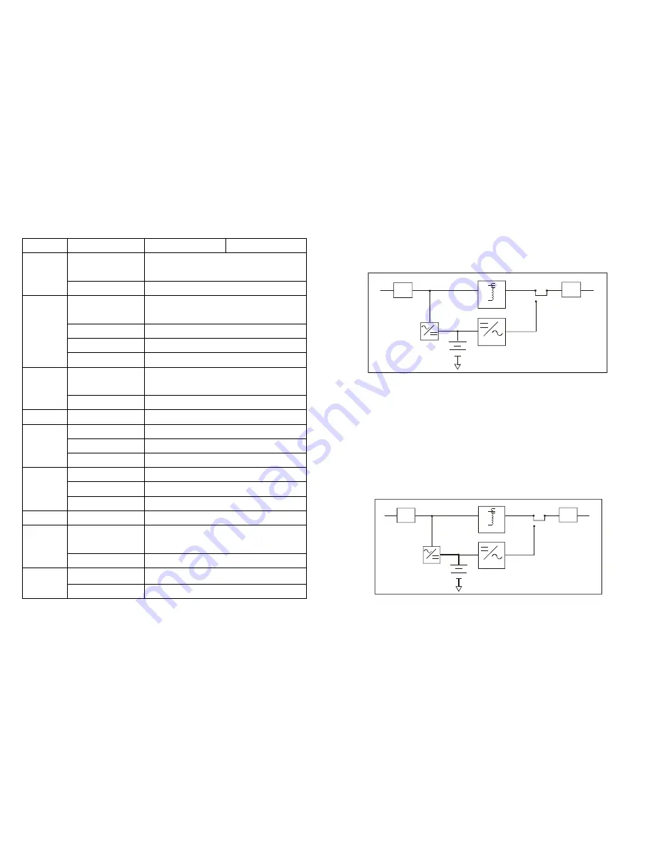
Fig. 1 shows how UPS works.
2. Normal Operation
There are two main loops when AC Utility normal the AC output loop and the
battery charging loop. The AC output gets power from AC utility input and
pass through AVR to support power to load. In the same time, the AC utility
input is converted by AC/DC CHA and support charging power to charge
batteries.
AVR.
INV.
CHA.
N.F.
N.F.
INPUT
OUTPUT
Fig. 2 shows how the UPS works when AC Utility normal.
- 3 -


