Owner‘s Manual Crimping Machine CM 25-1.3
Rev.: 2016-05-31
1 / 15
Please read instructions before starting any job!
Owner‘s Manual
Crimping Machine CM 25-1.3
Page 1: ...Owner s Manual Crimping Machine CM 25 1 3 Rev 2016 05 31 1 15 Please read instructions before starting any job Owner s Manual Crimping Machine CM 25 1 3...
Page 2: ...ices 7 7 3 Adjusting the Working Stroke 8 7 4 Exchange of Crimping Dies 9 7 5 Change of Crimping Position 10 7 6 Exchanging the Adapters for Larger System Measurements 11 7 7 Crimping Dimension Adjust...
Page 3: ...ess Unauthorized modifications to the machine including the safety devices will exclude the manufacturer from any liability The start of the operation of the machine can be triggered by foot pedal Opt...
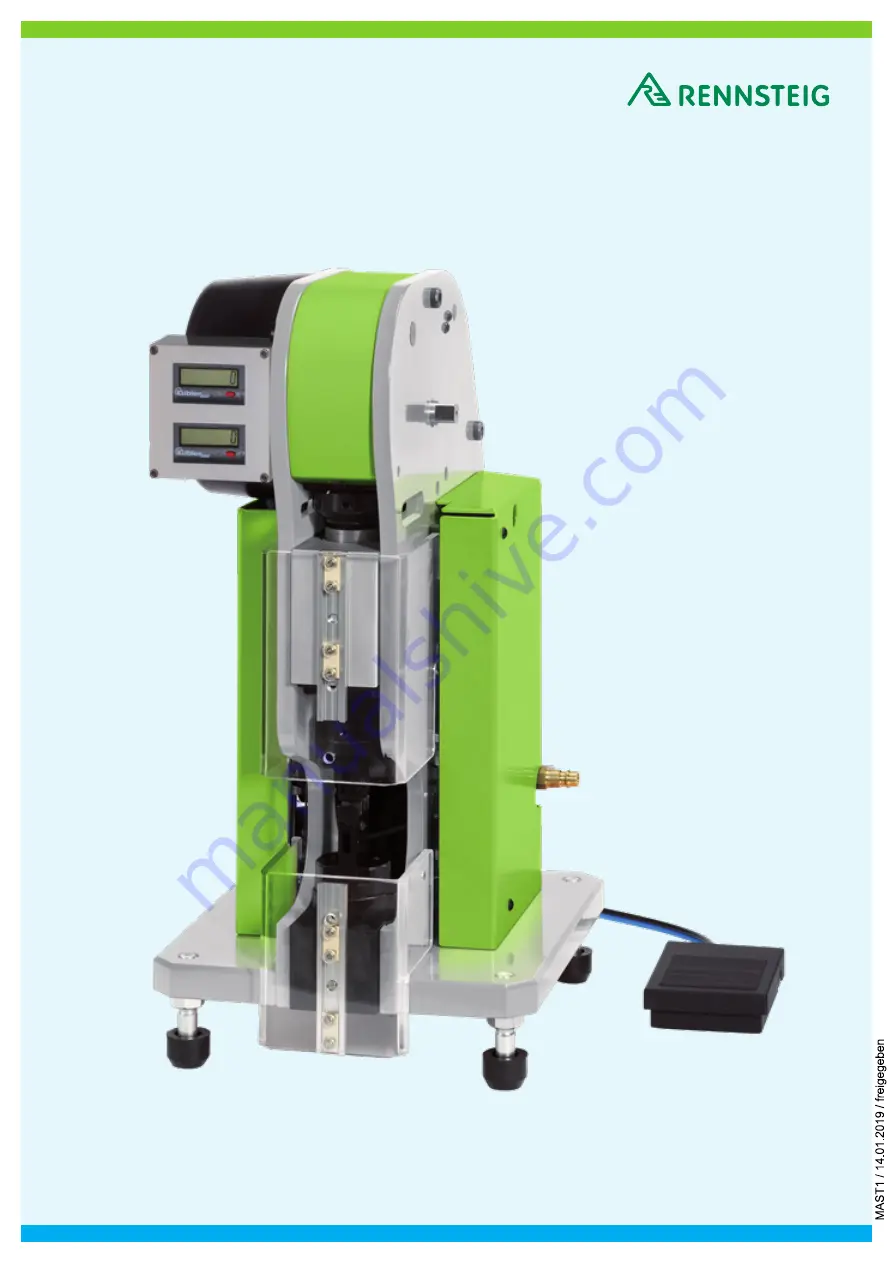
Page 4: ...ng Slide with adjusting collar and scale Swivel shaft to adjust working stroke Upper movable safety cover Upper and lower adapter for die set intake Crimping Die Set Lower movable safety cover Feet Pn...
Page 5: ...out later at the job site Attention 4 Limitations of Liability The manufacturer will not assume any responsibility for the following damages occurring because of Failure to follow the operating instr...
Page 6: ...oses for the compressed air The built in pressure gauge Fig 2 4 is set at the factory and limits the air pressure to a max of 6 bar Please ensure the proper connection of air supply hose In order to o...
Page 7: ...edal to trigger working stroke after the crimp process is completed disengage the foot pedal the machine will move to its starting position Remove the crimped contact Crimp processes whereby the worki...
Page 8: ...ning width of 6 mm or more see 7 2 Safety Mechanism The switch over to the other working stroke is done as follows Close the shut off valve Fig 3 1 disconnect the air supply then open the shut off val...
Page 9: ...mm Fig 4 1 open the crimping die by turning the wrench on the square counter bearing slightly Pull out the die set in the direction of the red arrows Fig 4 3 out of the adapters Fig 4 2 Place the new...
Page 10: ...n wrench through the bore hole in the lower safety cover Fig 5 1 Set crimping dies to the desired position in 22 5 increments locking function Inspect the correct fit of the crimping dies by lining up...
Page 11: ...towards the user Loosen the upper adapter with an Allen wrench SW 2 5 mm After loosening the screw turn back the adapter intake back by 90 Loosen the lower adapter through the bore hole in the lower...
Page 12: ...t the desired setting Fig 6 1 Turning the adjustment screw by one scale line will change the plunger stroke by 0 05 mm Upon completion of the alignment secure the adjusting ring Fig 6 3 by tightening...
Page 13: ...completed Pressure within the pneumatic system is not working correctly Pull out pressure regulator and adjust by turning Check pressure in the system setup to be 6 bar Foreign object in the crimping...
Page 14: ...Owner s Manual Crimping Machine CM 25 1 3 Rev 2016 05 31 14 15 9 Technical Documentation...
Page 15: ...ine 2011 65 EU DIN EN 12100 2010 Safety of Machines General Principles of Design Risk Assessment and Risk Reduction DIN EN ISO 13857 2008 Safety of Machines Safety distances to prevent upper and lower...