This is a publication by Conrad Electronic SE, Klaus-Conrad-Str. 1, D-92240 Hirschau (www.conrad.com).
All rights including translation reserved. Reproduction by any method, e.g. photocopy, microfilming, or the capture in electronic data
processing systems require the prior written approval by the editor. Reprinting, also in part, is prohibited. This publication represent
the technical status at the time of printing.
© Copyright 2015 by Conrad Electronic SE.
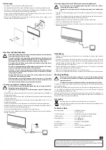
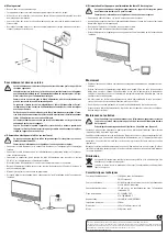
b) Wall mounting
• Drive two screws into the mounting surface.
• You can use the wall holder as template to mark the bores.
• Use the enclosed screws and, if necessary, wall plugs, or other screws/plugs that are appropri-
ate for the mounting surface to fasten the wall holder.
• Let the screw heads stick out a bit from the mounting surface, so that later the wall holder can
be hung from it.
• Mount the wall holder to the antenna as shown in the image and then hang the antenna on the
two screws.
Connection and start-up
Connect the antenna line of the antenna only to antenna inputs of corresponding re-
ceivers.
Use only the power adapter enclosed in the package in combination with the phan-
tom power adapter, which is also enclosed or the 5 V phantom power supply for your
receiver (if available) to supply the power.
The power supply may only be powered by a standard mains socket that is connected
to the public supply.
Be careful when handling mains cables and mains connectors. Mains voltage may
cause fatal electric shocks.
Make sure that the voltage indicated on the power supply corresponds with the mains
voltage of your power supply. Never try to operate the power supply at a different
voltage.
When making the connections, make sure that the connecting cables cannot be
pinched or damaged by sharp edges.
The mains socket to which the power adapter is connected must be near the device
and easily accessible, so that the device can be quickly and easily isolated from the
mains power supply in the event of any fault.
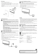
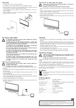
a) Voltage supply via the enclosed power pack unit
This connection type may only be used on receivers without phantom power or when
the 5 V phantom power supply is switched off.
Refer to your receiver’s operating instructions for further information.
• Connect the antenna line of the antenna with the antenna connection ANTENNA on the phan-
tom power adapter.
• Connect the short antenna line on the phantom power adapter to the antenna input of your
receiver.
• Connect the low voltage plug of the power supply to the DC 9~12 V connector on the phantom
power adapter.
• Plug the power supply into a wall outlet on the public power supply grid.
• As soon as the phantom power adapter is energized, the red indicator light goes on and on the
antenna the blue indicator will go on.
• Switch on your receiver and select a programme.
• Optimise reception by changing the mounting position or the direction of the antenna.
b) Powered by the 5 V phantom power of the receiver
This connection type is only suitable for receivers that feature 5 V phantom power for
antennas.
Refer to your receiver’s operating instructions for further information.
• Connect the antenna line of the antenna with the antenna input of your receiver.
• Switch on your receiver and activate the phantom power for the antenna input (see operation
instructions of the relevant device).
• As soon as the antenna is energized, the blue operating indicator will go on.
• Select a program on the receiver.
• Optimise reception by changing the mounting position or the direction of the antenna.
Handling
• Never operate the antenna or the power pack if the housing is damaged or covers are missing.
• Never use the antenna and the power supply immediately after taking it from a cold room into a
warm one. The condensation that forms can ruin the product under certain circumstances. Let
it reach room temperature first. Wait until the condensation has evaporated.
• Never unplug power supplies from the mains socket by pulling on the cable; always use the
provided handles which are intended specifically for this purpose.
• Unplug the power supply if you are not going to use the device for a while.
• For safety reasons, disconnect the power adaptor from the mains socket during thunderstorms.
Maintenance and care
Before cleaning the product, disconnect it from the power supply (unplug the power
supply from the mains socket or the antenna jack from the receiver if phantom power
is used!).
Absolutely prevent wetness or dampness from penetrating into the device.
The antenna is maintenance-free; therefore, never open the housing. If you do open it, the warran-
ty will be rendered null and void.
Periodically inspect the technical safety of the device for damage to the case, power supply, etc. If
the unit is damaged, it must be put out of operation and secured against accidental use.
The outside of the casing should be cleaned only with a dry, soft cloth or brush. Never use aggres-
sive cleansing agents or chemical solutions, since they might damage the surface of the housing.
Disposal
Electronic devices are recyclables and must not be disposed of in household waste!
Please dispose of the product, when it is no longer of use, according to the current
statutory requirements.
Technical data
Operating voltage.........................................230 V/50 Hz (power supply)
.........................................................................
5 V/DC (Antenna)
Power consumption.....................................0.2/0.9 W (standby/max.) when using power supply
Input current .................................................55 mA for 5 V phantom supply
Reception band ............................................47 - 230 MHz VHF
.........................................................................
470 - 790 MHz (UHF)
Gain ................................................................20 ±3 dB/16 ±4 dB (VHF/UHF)
Connection impedance ...............................75 Ohms
Dimensions.................................................... 285 x 147 x 80 mm (with stand)
Weight ............................................................approx. 320 g (with stand)


