


22
TONiC RESM20 angle encoder system installation guide
Output specifications
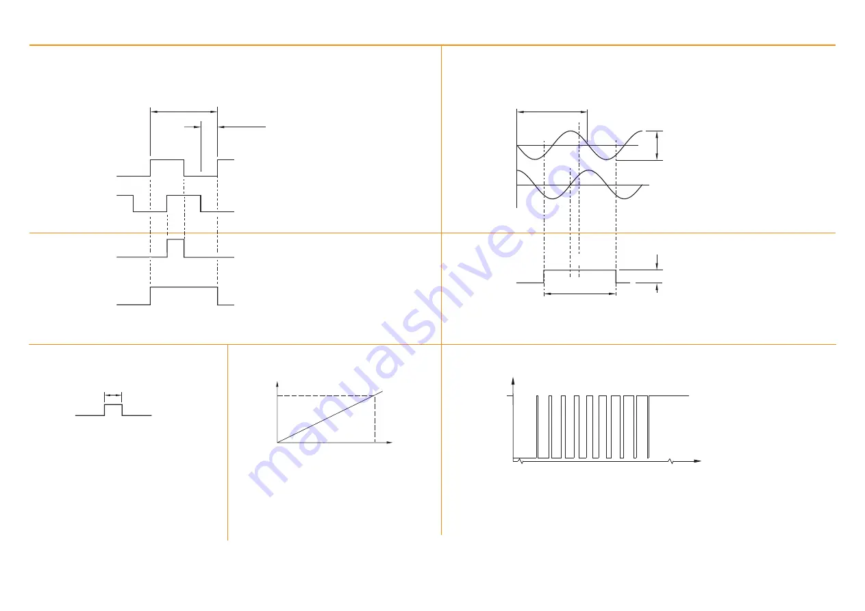
Digital output signals
Form – Square wave differential line driver to EIA RS422A (except limits P and Q)
20 µm
45°
Analogue output signals
Incremental
2 channels V
1
and V
2
differential sinusoids in quadrature (90° phase shifted)
(V
1
+)−(V
1
−)
(V
2
+)−(V
2
−)
Bi-directionally repeatable.
Differential pulse V
0
, centred on 45°
(V
0
+)−(V
0
−)
Reference
0.8 to 1.2 Vpp
360° (nom)
0°
Reference
†
Incremental
2 channels A and B in quadrature (90° phase shifted)
Signal period
Resolution
A
B
Z
Z
Synchronised pulse Z, duration as resolution
Synchronised pulse Z, duration signal period
Wide reference
†
Set-up*
* Set-up signals as shown are not present during calibtation routine.
†
Inverse signals not shown for clarity
Alarm
†
Asynchronous pulse
Line driven
E
> 15 ms
0
Set-up*
Voltage
at X
1
100%
0
Signal level
Setup signal voltage proportional to
incremental signal amplitude
0.7 to 1.35 Vpp with Green LED indication,
(readhead) and 120R termination.
Centred on 1.65 V
NOTE:
Ti0000A00V centred on 2.5 V
NOTE:
Select ‘standard’ or ‘wide’ reference at time of ordering, to match the requirements of the controller
being used. Wide reference mark not available on Ti0004 interfaces.
Alarm asserted when:
–
Signal amplitude < 20% or > 135%
– Readhead speed too high for reliable operation
E− output only for Ti options A, B, C, D
or 3-state alarm
Differentially transmitted signals forced open circuit
for > 15 ms when alarm conditions valid.
Voltage
at V
X
3.3 V (nom)
50%
70%
100%
0
0
Signal level
Between 50% and 70% signal level, V
X
is a duty cycle.
Time spent at 3.3 V increases with incremental signal level.
At > 70% signal level V
X
is nominal 3.3 V.