2. Preparing the Evaluation Board Kit
3.
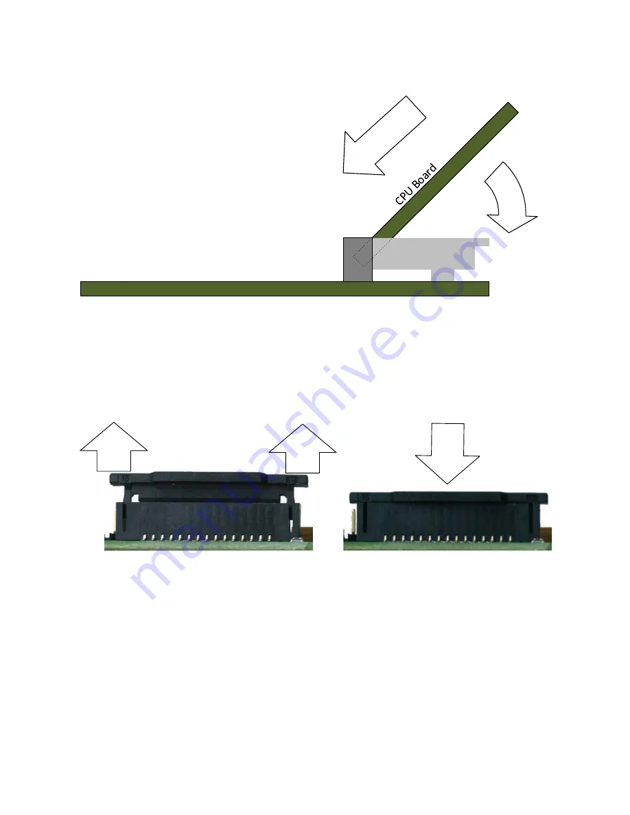
Connect the CPU board to the sub board using the 204-pin connector (note the key slot is to the left of centre).
Orientate at approximately 45° from horizontal, inserting the edge connector fully into the socket before gently
rotating the CPU board down flat until the clamps lock the board in place.
2
1
Sub Board
CN1
Actions for inserting CPU
Board in Sub Board CN1
4.
Connect the Display Output Board to the display connector (CN15 LCD) on the sub board. The central key ensures
correct orientation by aligning it with the slot in the socket.
5.
Connect the Display Output Board to an external monitor capable of 800x600 resolution using a monitor cable (not
supplied).
6.
Connect the camera module to the camera connector (CN2 MIPI) on the CPU board.
Open the connector by pulling up on the tags at either side, then insert the camera’s ribbon cable. The correct
orientation is with the contacts on the ribbon cable facing the CPU, and the blue insulated rectangle to the outside.
To hold the cable firmly, push down on the top of the connector until it clips in place.
Pull tags to open
Push centre
to close
7.
Connect the J-Link LITE Segger debugger module to the debugger connector (CN5 Coresight 20) on the CPU
board using the ribbon cable. Ensure that pin 1 (red strand) mates with the triangle mark ► on the PCB silk screen.
8.
Connect the debugger module to a USB port on the host PC. The green LED on the debugger will illuminate.
9.
The debugger drivers will now be installed. Note that, this may take up to a minute and administrator privileges will
be required.
Windows™ 7
Windows™ 8.1 / 8
Windows™ 10
“Device driver software installed
successfully” pop-up will appear in
the Windows™ Taskbar and
installation will complete.
An icon will appear in the Windows™
Taskbar and installation will
complete.
A Windows™ taskbar buttons of
“Device Setup” will appear in the
Windows™ Taskbar and installation
will complete.


