1. Installation
You can run the installation first, or come back and run it later if you wish to use the pre-programmed on-
board demo. However, if the USB driver is not automatically installed after connecting to the RPB you will
need to perform the installation before proceeding.
The installer will install all of the tools for your Renesas Promotional Board.
1.
Insert the mini CD into your computer’s CD-ROM drive. The CD should automatically run the installation
program. If the installer does not start, browse to the CD root folder and double click on ‘setup.exe’.
2.
Windows™ Vista users may see “User Account Control” dialog box. If applicable, enter the administrator
password. Click <OK>
3.
Follow the on-screen instructions until the installation is completed.
Note: The Windows driver signing dialog box may be displayed. Please accept the driver to continue.
4.
Note that the first time the board is connected to each USB port, J-Link will install its driver automatically and
Vista users may need to enter an administrator password during this process.
5.
Note that these demonstration programs support little endian configuration.
2. Initial board configuration and connection for the pre-programmed
on-board demonstration
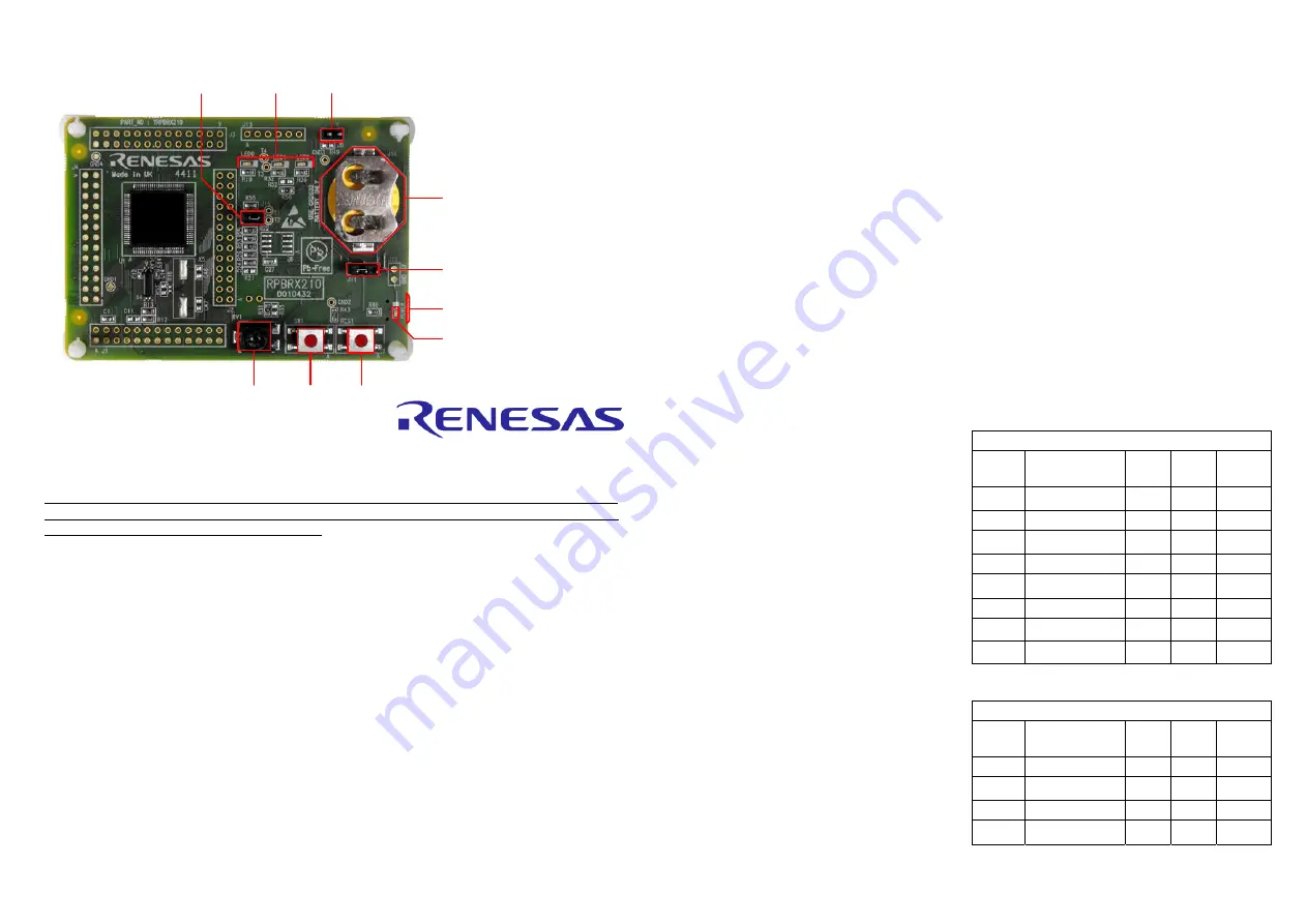
J6 (fitted): MCU Power. Although this jumper is fitted by default, it can be replaced with an ammeter to measure
the CPU current.
J11 (2-3): Power Source Select. By default, this will be connected between pins 2 and 3 to select USB power.
J15 (fitted): Debugger Disable. The RPBRX210 includes a debugger circuit that can be used to program and
debug the RX210 but this circuit is disabled byJ15 by default to allow execution of the the pre-programmed on-
board demonstration. In this configuration, the USB connection will not support debugging and will instead just be
used to power the board.
Quick Start
Renesas Promotional Board
For RX210
The board is pre-programmed with the in the Low Power Demonstration program.
User LEDs
For running the code (including the the pre-programmed on-board demonstration) without debugging:
6.
Ensure that the J15 jumper is fitted to disable the debugger circuit.
7.
Ensure that the J11 jumper is fitted between pins 2 and 3 to enable USB as the power source.
8.
Either ensure that the J6 jumper is fitted, or remove the jumper from J6 and connect an ammeter to measure
the MCU current.
9.
Plug in the USB cable between the PC and the RPB to power the board and execute the pre-programmed
demo code. Note that the USB connector is on the underside of the board. The power LED indicator should
light and the code will begin execution, see section 3 for instructions for operation of the demonstration
program.
3. LowPowerDemo program operation
The RPB uses three LEDs for visual output and a switch and potentiometer for the control input. The user
interface for configuring the tutorial code is via a "menu" system where the options are adjusted using the
potentiometer, displayed in binary on the LEDs, and selected using SW1. More detail on the available
settings can be found in the appendix.
Using the demo:
10.
Before the main menu selection, the LEDs will firstly display a moving pattern for a couple of seconds to
identify that this is the first menu.
11.
When this is complete, the user can select a
value from 0 to 7 with the potentiometer. As the
potentiometer is adjusted, the corresponding
value will be displayed in binary on the LEDs.
Note that LED0 is the least significant bit but is
on the left side of the RPB.
12.
The options that can be selected from the main
menu are as follows, and selection is made with
a short press of switch SW1. LED0 will then
flash the appropriate number of times to confirm
the selection.
13.
Only if option 0 was selected, then the next
menu selection is for the RTC options. Again the
selection is made with the potentiometer and
Switch SW1. The options are shown to the right.
After the RTC menu selection, operation will
return to step 10.
*For Output RTC, the hours, minutes and
seconds value will be indicated by flashes on
LED0, LED1 and LED2 respectively.
Main Menu Options
Value
Name
LED0
(lsb)
LED1 LED2
(msb)
0
RTC_MENU
0
0 0
1
SUB_32k
1
0 0
2
LOCO_125k
0
1 0
3
HOCO_1M
1
1 0
4
HOCO_50M
0
0 1
5
SW_SLEEP
1
0 1
6
SW_STBY
0
1 1
7
SW_DP_STBY
1
1 1
RTC Menu Options
Value
Name
LED0
(lsb)
LED1 LED2
(msb)
1
Output RTC*
1
0 0
2
Reset RTC
0
1 0
3
Start RTC
1
1 0
4
Stop RTC
0
0 1
Battery Holder
USB Connector
SW1
Switch
Reset
Switch
Potentiometer
J11
J6
J15
Power LED
Summary of Contents for Promotional board
Page 7: ......


