background image


5.2. Connecting the debugger 

For this tutorial it is not necessary to provide an external power supply to the board. The power will be obtained from the USB port. Please 

be aware that if you have too many devices connected to your USB port it may be shut down by windows. If this happens remove some 

devices and try again. Alternatively provide an external power source taking care to ensure the correct polarity and voltage. 

The Quick Start Guide provided with the Renesas Starter Kit board gives detailed instructions on how to connect the E8a to the host 

computer. The following assumes that the steps in the Quick Start Guide have been followed and the E8a drivers have been installed. 


Fit the LCD module to J8 on the Renesas  Starter  Kit, so it lies above J1. Insure all the pins of the connector are correctly 

inserted in the socket. 


Connect the E8a debugger to the USB port on your computer. 


Connect the E8a Debugger to the target hardware ensuring that it is plugged into the connector marked E8 which is nearest 

the power connector. 


If supplying external power to the board this can be turned on now. 

5.3. Connecting to the target with the E8a 

This section will take you through the process of connecting to the device, programming the Flash and executing the code. 


Select the ‘SessionM16C_E8a_SYSTEM’ debug 

session. 


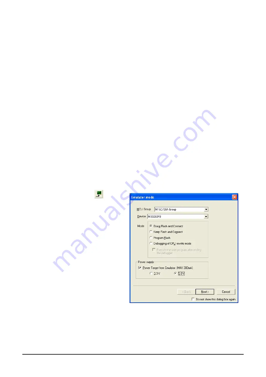
Click the <Connect> button   

on the debug toolbar 


The ‘Emulator mode’ dialog will be shown. Select 

the correct MCU group and device type (e.g. 

M16C/26A Group and M30260F8 for 

E8A_RSKM16C26A). 


Select ‘Erase Flash and Connect’. 


If the E8a is to provide power to the board, set 

‘Power Target from Emulator’ and  choose  the 

‘5.0V’ option. 

Otherwise connect a 5V centre positive supply. 


Click <Next>. 


Summary of Contents for M16C/26A

Page 1: ...ok over all the business of both companies Therefore although the old company name remains in this document it is a valid Renesas Electronics document We appreciate your understanding Renesas Electron...

Page 2: ...t for an application categorized as Specific or for which the product is not intended where you have failed to obtain the prior written consent of Renesas Electronics The quality grade of each Renesas...

Page 3: ...Renesas Starter Kit for M16C 26A Tutorial Manual User s Manual Rev 4 00 2007 10 RENESAS 16 BIT SINGLE CHIP MICROCOMPUTER M16C FAMILY M16C Tiny SERIES...

Page 4: ...uration 5 4 3 2 Debug Session 5 Chapter 5 Building the Tutorial Project 6 5 1 Building Code 6 5 2 Connecting the debugger 7 5 3 Connecting to the target with the E8a 7 Chapter 6 Downloading and Runnin...

Page 5: ...stered trademarks of their respective companies or organisations Copyright Renesas Technology Europe Ltd 2007 All rights reserved Renesas Solutions Corporation 2007 All rights reserved Renesas Technol...

Page 6: ...d demonstrating code suitable for release in a product Files referred to in this manual are installed using the project generator as you work through the tutorials The tutorial examples in this manual...

Page 7: ...onfiguration menu in High performance Embedded Workshop allows the project to be configured such that certain files may be excluded from each of the build configurations This allows the inclusion of t...

Page 8: ...e from the File New Workspace menu or select Create a new project workspace when presented with the Welcome dialog The example above shows the New Project Workspace dialog with the RSKM16C26A selected...

Page 9: ...ns two build configurations and two debug sessions The Build Configuration allows the same project to be built but with different compiler options The options available to the user are described fully...

Page 10: ...ions on each of the tabs and Category drop down lists to be aware of the options available When complete close the dialog box by clicking OK There are three short cuts available for building the proje...

Page 11: ...lies above J1 Insure all the pins of the connector are correctly inserted in the socket Connect the E8a debugger to the USB port on your computer Connect the E8a Debugger to the target hardware ensur...

Page 12: ...ox Debugging of program that uses WDT is not checked Click Next Only Single Chip Mode is available Clear PM10 b0 of 000005H is 1 Click Finish The Flash Memory write program is downloaded The Output wi...

Page 13: ...ht click on the download module listed and select Download On completion the debugger and code are ready to be executed To start debugging we need to reset the debugger and target Press Reset CPU on t...

Page 14: ...int Alternatively set an eventpoint by clicking in the column to the left of the breakpoint column Up to 6 eventpoints can be set Eventpoints do not require programming the flash memory and thus are f...

Page 15: ...In the TimerADC code the interrupt reads the last ADC conversion from the external potentiometer and uses the result to set the next compare match value The ADC conversion is then re started The inte...

Page 16: ...LED test Press Step In on the Debug Tool Bar It is possible to monitor variables during debugging of the code To set up a watch on a variable place the mouse over the variable If the variable is avai...

Page 17: ...unction call after the loop and select Go to cursor This shows that the variable was initialised at program start up and can be overwritten with TESTTEST You have now run the tutorial code and used ma...

Page 18: ...text describing the function of each code entry Please refer to the source code for greater detail on the purpose and operation of the compiler specific details 7 1 1 Initialisation code resetprg c r...

Page 19: ...up h There are four common stages to the configuration of the microcontroller device The code to demonstrate this is therefore split into four functions Each function is written specifically for the d...

Page 20: ...is common to all tutorial projects The display initialisation and string display functions operate on the LCD display module Check compatibility with ks0066u controller and pin connection on the schem...

Page 21: ...ation available for this product can be found on the Renesas website at www renesas com renesas_starter_kits General information on Renesas Microcontrollers can be found at the following website Globa...

Page 22: ...blication Date Rev 4 00 Oct 22 2007 Published by Renesas Technology Europe Ltd Dukes Meadow Millboard Road Bourne End Buckinghamshire SL8 5FH UK 2007 Renesas Technology Europe Ltd Renesas Solutions Co...

Page 23: ...1753 Shimonumabe Nakahara ku Kawasaki shi Kanagawa 211 8668 Japan Renesas Starter Kit for M16C 26A REG10J0041 0400 Tutorial Manual...

Reviews: