- 3 -
www.rotork.com www.remotecontrol.se
1. Fail Close
When there is no input signal, the actuator automatically turns to a full close position.
2. Fail Open
When there is no input signal, the actuator automatically turns to a full open position.
3. AF
If the input signal is at 3.8 ~ 4.3mA, the actuator turns to a full close position.
If the input signal is at 19.7 ~ 20.2mA, the actuator turns to a full open position.
4. CH1
Optional modulation
It is used when the user voluntarily changes the input signal.
ex) When setting to 6 ~ 18mA Input
●
CH1 ON
→
Input 6mA and press ZERO button
→
Input 18mA and press SPAN button.
→
CH1 OFF
→
Input and check if the device operates normally.
5. CH2
Optional modulation using manual handle.
Ii is used when the user controls the actuator using the manual handle.
ex) When controlling using the manual handle.
●
CH2 ON
→
Put the actuator at Full Close.
→
Press the ZERO Button
→
Put the actuator at
Full Open
→
Press the SPAN Button
→
CH2 OFF
→
Input and check if the device operates
normally.
6. REV
It is used when the actuator operates in the inverse direction.
When REV is on and at 4mA, the actuator turns to a full open position, and to a full close position
when at 20mA.
7. Full Close
Output Control
If the output is 3.7mA (not 4mA), put no.7 switch up and put SPAN button.
Whenever the button is put, the output increase. When it reaches at 4mA, put ASCN button for a
second to save it.
(If the output is higher than 4mA, (4.2mA), put ZERO button to decrease.)
8. Full Open
Output Control
If the output is not 20mA, follow the same step as above (7. Full Close Output Control).
↑
+
−
↑
↑
+
−
↑
3
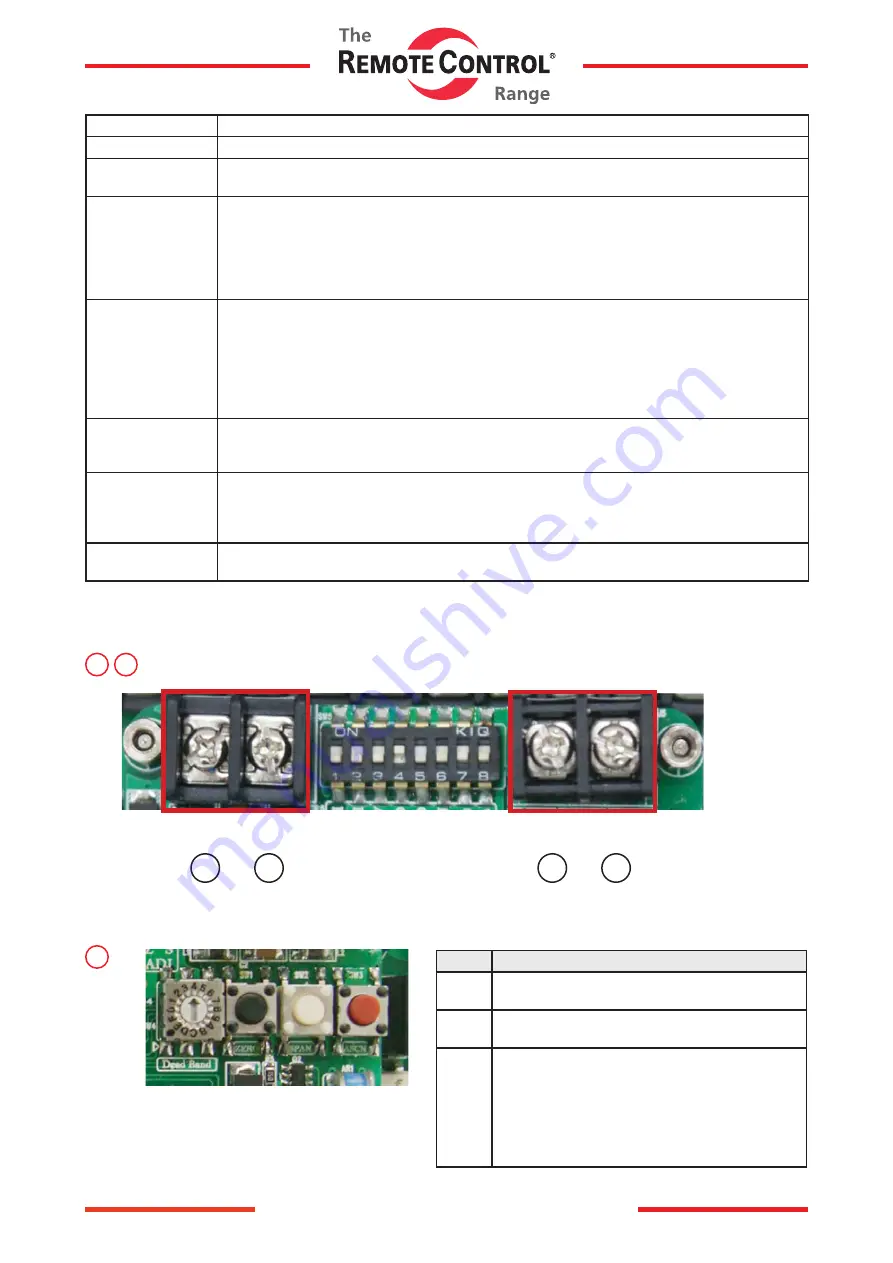
In / Output Connector
7
4
Name
Spec.
ZERO Close manual control button
/ Input module button
SPAN Open manual control button
/ Input module button
ASCN AUTO SCAN BUTTON
(Actuator automatic control button)
Delivered from the factory the resistance value
of potentiometer may can be changed if the user
modifies its limit setting. Please make sure to
press the autoscan button for at least 2 seconds
before operating proportional control.


