


Before commissioning
After the tightness check has
been successfully completed,
connect the vacuum pump via the
pressure gauge station to the valve
connections on the outdoor unit
(see chapter "Tightness check")
and create a vacuum.
Perform the following checks
prior to commissioning the
unit for the first time and after
any interventions affecting the
refrigerant circuit. Record the
results in the commissioning
report:
■
Check of all refrigerant pipes
and valves with leak detection
spray or soapy water for leaks
and for inadvertent mix up of
suction and injection pipe, with
the unit at a standstill.
■
Check of all refrigerant pipes
and insulation for damage.
■
Check of all electrical
connections between indoor
unit and outdoor unit for
correct polarity.
■
Check that all fastenings,
mountings etc. are firm and at
the correct level.
Commissioning
Commissioning should only be
performed and documented by
specially trained personnel.
Observe the manuals for the
indoor unit and outdoor unit
when commissioning the
entire system.
NOTE
The system can be commissioned
once all the components have
been connected and checked.
A functional check should be
performed to verify its correct
function and identify any unusual
operational behaviour prior to
handing it over to the operator.
This check is dependent on the
installed indoor unit.
The procedures are specified in the
manual for the indoor unit being
commissioned.
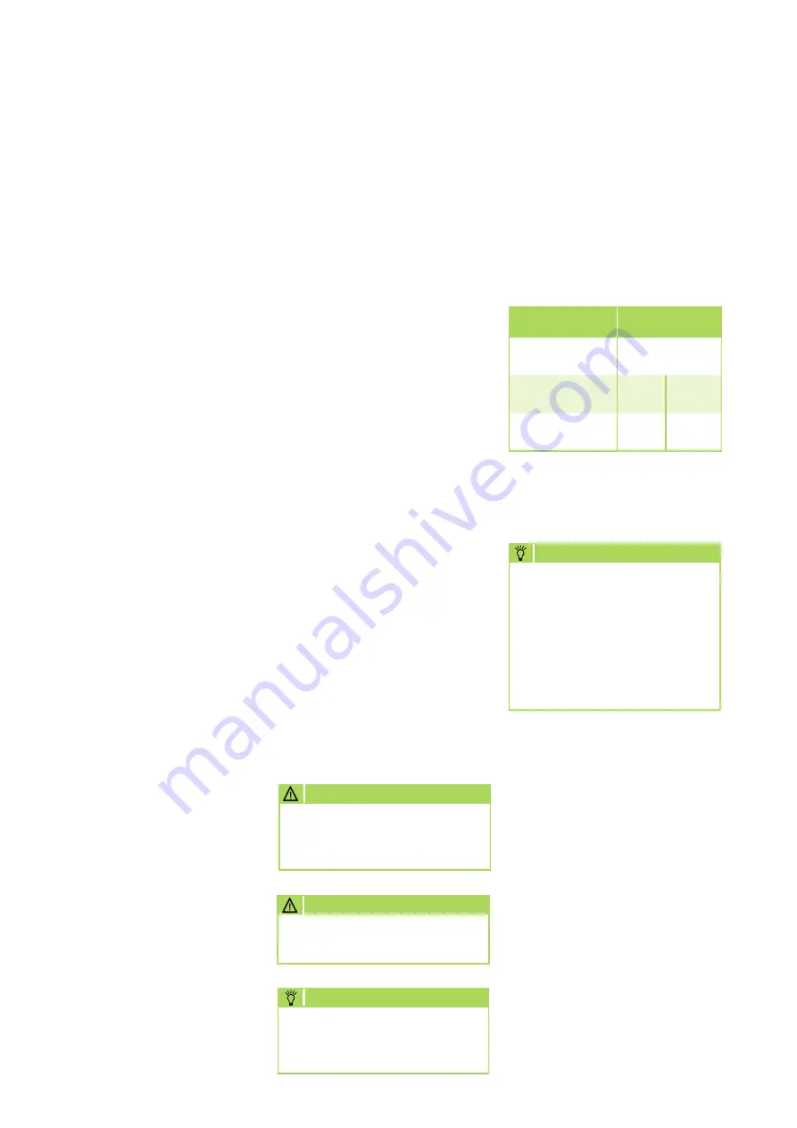
Add refrigerant
The unit contains a basic quantity
of refrigerant.
In addition, an additional amount
of refrigerant must be added for
refrigerant pipe lengths exceeding
5 meters per circuit. Refer to the
following chart:
Note that the employed
refrigerant is always filled in
liquid form!
CAUTION
NOTE
Check the overheating to
determine the refrigerant fill
quantity.
Wear protective clothing when
handling refrigerant.
CAUTION
MVT
600 DC - 1050 DC
Basic pipe length
Additional
filling quantity
Up to and incl.
5 m
0 g/m
0 g/m
5 m to max. 15 m
per circuit
30 g/m
30 g/m
Condensate connection
and safe drainage
Condensate connection
If the temperature falls below the
dew point, condensation will form
on the finned condenser during
heating mode
.
Below the register is a collection
tray, which must be connected to
a drain.
■
The condensate line should
have a fall of min. 2 %.
This is the responsibility of the
customer.
If necessary, fit vapour diffusion
proof insulation.
■
When operating the unit at
outdoor temperatures below 4 °C,
make sure to route the condensate
line so that freezing is prevented.
The lower part of the housing
must also be kept frost free by the
user, in order to ensure permanent
draining of the condensate.
If necessary, fit a pipe heater.
■
After installation is complete,
check for unobstructed
condensation run off and
ensure that a permanent seal is
provided.
Safe drainage in the event of
leakage
Local regulations or environmental
laws, for example the German Water
Resource Act (WHG), can require
suitable precautions to protect
against uncontrolled drainage in
case of leakage to provide for safe
disposal of escaping air conditioning
fluid or hazardous media.
REMKO MVT
20


