background image

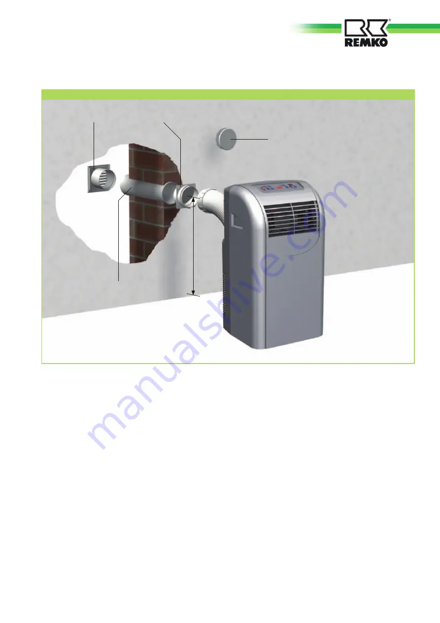
Installation scheme of the wall through (optional)

Installation Instructions

1.  Create a core hole in the out-

side wall (max.- wall thickness 
of 480 mm) with a diameter of 
at least 135 mm.
Note possible supply lines in 
this area!

2.  Insert the telescopic pipe in the 

created wall opening so that is 
the outer pipe (large diameter) 
on the inside wall.  
To prevent cold bridges, insu-
late the telescopic pipe with 
suitable insulating material. 

3.  Wall the telescopic pipe into the 

core hole in such a way that it is 
flush to both sides of the wall.

4.  Mount the protection grill on 

the outside of the wall with 4 
screws (make sure it is protect-
ed from rain).

5.  Fix the trap to the inside and 

mount it with 4 screws..
The “top“ label on the trap 
must be legible from the inside!

6.  When taking the device out 

of service, for example, at the 
beginning of winter, close the 
opening of the trap using the 
sealing cap to prevent air circu-
lation.

Sealing cap

Trap

Protection grill

Telescopic pipe

min. 400 mm

Installation example

11

Summary of Contents for MKT 290 S-Line

Page 1: ...Ausgabe GB W12 REMKO MKT MKT 290 MKT 290 S Line Mobile Air Conditioner Operation Technology Spare Parts ...

Page 2: ......

Page 3: ...liability accepted for errors or misprints Safety notes 4 Environmental protection and recycling 4 Warranty 4 Intended use 4 Transport and packaging 5 Equipment description 5 Operation 6 7 Bevore Commissioning 8 9 Commissioning 9 Shut down 9 10 Care and maintenance 10 Installation scheme of the wall through optional 11 Troubleshooting and customer service 12 Electrical connection diagram 13 Explod...

Page 4: ... not permitted and can cause malfunctions Equipment and components may not be operated in areas where there is an increased risk of damage Observe the mini mum clearances The electrical supply is to be adapted to the requirements of the equipment The operational safety of equip ment and components is only assured if they are fully as sembled and used as intended Safety devices may not be modi fied...

Page 5: ... setting up on the floor indoors and has an exhaust tube to dissipate the heat The indoor unit will located in the room to be cooled heat in the evaporator heat exchanger and transfers it to the internal cooling circuit This is the heat of a further heat exchanger condenser via the flexible exhaust hose into the open again The condensate collected during cooling operation is transported to the out...

Page 6: ...ts up the current room temperature is shown in the display Green Set Temp LED C F toggle button only on the remote control Control panel Mode selection Cool The device is used to cool the room It filters and dehumidifies the air and thus creates a pleas ant room climate Dehumidify In the Dehumidify mode hu midity is removed from the air Fan The device circulates the air filters it and creates an e...

Page 7: ... Press the Mode button until the Fan LED lights up 3 Select the fan setting using the Fan Speed button High highest speed Med medium speed Low lowest speed 4 The room temperature is not in fluenced and remains constant For this reason the tempera ture and time setting Timer Temp Adjust buttons cannot be used Timer time delay You can turn the device on and off automatically using the timer To do so...

Page 8: ...he power line must have a correct cross section and may be used only fully rolled out Never operate the unit with out the intake filter Without an air intake filter the plate fins of the eva porators be come dirty and the unit s performance is adver sely affected Make sure that people and objects such as plants in the room are not directly in the path of the expelled air Condensa tions drain with ...

Page 9: ...mance of the unit is adversely affected as a result make sure that the pressure is corrected NOTE Shut down Temporary Shut down If the unit is to be taken out of operation for a longer period of time for example over the winter proceed as follows 1 Let the device run for appro ximately 2 hours in circulation mode FAN to dry the surface of the evaporator plate fins This removes the remaining moistu...

Page 10: ...lukewarm soap solution Fig 6 5 Let the filter air dry 6 Replace the filter in the unit Fig 4 7 Make sure that the filter is dry and undamaged Never operate the unit without the air filter 5 Cleaning with a vacuum cleaner 6 Cleaning with lukewarm water CAUTION Care and maintenance Regular care and observation of some basic points will ensure trouble free operation and a long service life of the uni...

Page 11: ... suitable insulating material 3 Wall the telescopic pipe into the core hole in such a way that it is flush to both sides of the wall 4 Mount the protection grill on the outside of the wall with 4 screws make sure it is protect ed from rain 5 Fix the trap to the inside and mount it with 4 screws The top label on the trap must be legible from the inside 6 When taking the device out of service for ex...

Page 12: ...en properly attached It may not be bent declining or laid in a tight curve no foreign bodies impair the exhaust or intake air supply observe the minimum clearances the air directing plate fins are free of soiling or foreign objects the set temperature is not too high operating limits of the device 16 to 35 C The device does not react to the remote control Make sure that the batteries are functioni...

Page 13: ...enser Rot Orange Gelb White Red Red Red Blue Compressor Reservoir condenser motor Mains plug Micro switch Reservoir Temperature sensor J003 J002 J001 Hi Med Lo RL101 L N E J01 Brown L COMP L Blue Blue Blue Blue White Blue White Condenser Condenser Evaporator fan 13 ...

Page 14: ...29 30 17 18 25 19 20 15 24 32 22 8 10 9 5 16 7 6 21 4 13 14 11 26 27 12 23 1 2 3 33 We reserve the right to modify the dimensions and constructional design as part of the ongoing technical development process REMKO MKT 14 ...

Page 15: ...6896 1106896 18 Fan housing circulation air 1106822 1106822 19 Fan wheel circulation air 1106823 1106823 20 Fan motor circulation air 1106843 1106843 21 Circuit board 1106873 1106873 22 Mains supply line with plug 1106874 1106874 23 Front wall 1106820 1106827 24 Back wall 1106829 1106829 25 Air outlet segment 1106844 1106844 26 PCB with control 1106825 1106825 27 Control panel 1106826 1106831 28 A...

Page 16: ...gerant R 410A Operating pressure max cooling circle kPa 1800 3600 Refrigerant quantity kg 0 65 Circulation air volume flow rate m h 240 270 320 Sound pressure level 2 dB A 45 50 53 Voltage supply V Hz 230 1 50 Type of protection IP 20 Power consumption 1 kW 1 09 Current consumption 1 A 4 93 Electrical starting current A 21 Air outlet hose diameter mm mm 1200 125 Diemsions Height mm 700 Width mm 43...

Page 17: ...ting technology Im Seelenkamp 12 D 32791 Lage Equipment machinery Implementation Mobile Air Conditioning Unit for cooling Series Model REMKO MKT 290 MKT 290 S Line Series Class Number 772 and 773 Applicable regulations MA RL 2006 42 EC Machinery Directive EC Directive NS RL 2006 95 EC Low Voltage Directive EMC RL 2004 108 EEC EMC Directive EnVKV RL 92 75 EEC Energy consumption labelling directive ...

Page 18: ...Notes ...

Page 19: ......

Page 20: ...er Lieferant REMKO ein Partner der Probleme lösen hilft Der Vertrieb REMKO leistet sich nicht nur ein gut ausgebautes Vertriebsnetz im In und Ausland sondern auch ungewöhnlich hochqualifizierte Fachleute für den Vertrieb REMKO Mitarbeiter im Außen dienst sind mehr als nur Verkäufer vor allem müssen sie für unsere Kunden Berater in der Klima und Wärmetechnik sein Der Kundendienst Unsere Geräte arbe...

Reviews: